


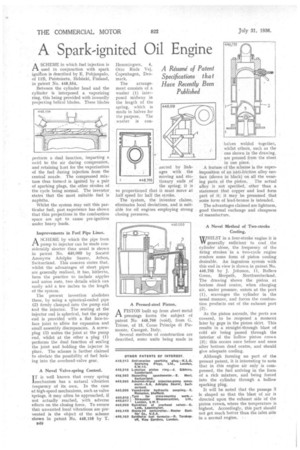
A Spark-ignited Oil Engine A SCHEME in which fuel injection is
Page 46
If you've noticed an error in this article please click here to report it so we can fix it.
used in conjunction with spark ignition is described by E. Pohjanpalo, of I1B, Puistokatu, Helsinki, Finland, in patent No. 498,554.
Between the cylinder head and the cylinder is interposed a vaporizing ring, this being provided with inwardly projecting helical blades. These blades perform a dual function, imparting a swirl to the air during compression, and retaining heat for the vaporization of the fuel during injection from the central nozzle. The compressed mixture thus formed is ignited by a pair of sparking plugs, the other strokes of the cycle being normal. The inventor states that the most suitable fuel is naphtha.
Whilst the system may suit this particular fuel, past experience has shown that thin projections in the combustion space are apt to cause pre-ignition under heavy loads.
Improvements in Fuel Pipe Lines.
A SCHEME by which the pipe from Pt pump to injector can be made considerably shorter than usual is shown in patent No. 448,089 by Societe Anonyme Adolphe Sauter, Arbon, Switzerland. This concern states that, whilst the advantages of short pipes are generally realized, it has, hitherto, been the practice to include nipples and union nuts, two details which can easily add a few inches to the length of the system.
The present invention abolishes these, by using a spherical-ended pipe (2) firmly damped into the pump end and the injector. The seating at the injector end is spherical, but the pump end is provided with a flat face-toface joint to allOw for expansion and small assembly discrepancies. A screwplug (3) unites the joint at the pump end, whilst at the other a plug (1) performs the dual function of sealing the joint and holding the injector in place. The scheme is further claimed to obviate the possibility of fuel leaking into the overhead-valve gear.
A Novel Valve-spring Control.
IT is well known that every spring lmechanism has a natural vibration frequency of its own. In the case of high-speed mechanisms, such as valve Springs, it may often he approached, if not actually reached, with adverse effects on the dosing force. To ensure that unwanted local vibrations are prevented is the object of the scheme shown in patent No. 448,158 by T.
B40 Hemmingsen, 4, Otto Ruds Vej, Copenhagen, Denmark.
The arrangement consists of a washer (1) interposed midway in the length of the spring, which is made in halves for the purpose. The washer is con . aected by linkages with the moving and stationary ends of the spring; it is so proportioned that it must move at half speed for half the stroke.
The system, the inventor claims, eliminates local deviations, and is suitable for oil engines employing strong closing pressures.
A Pressed-steel Piston,
A PISTON built up from sheet metal I-1 pressings forms the subject of patent No 498,766 (void), from G. Trione, of 15, Corso Principe di Piemonte, Cuorgme, Italy.
Several methods of construction are described, some units being made in halves welded together, whilst others, such as the one shown in the drawing, are pressed from the sheet in one piece.
A feature of the scheme is the superimposition of an anti-friction alloy surface (shown in black) on all the wearing parts of the piston. The actual alloy is not specified, other than a statement that copper and lead form part of it; it may be presumed that some form of lead-bronze is intended.
The advantages claimed are lightness, good thermal exchange and cheapness of manufacture.
A Novel Method of Two-stroke Cooling.
WHILST in a four-stroke engine it is VV generally sufficient to cool the cylinder alone, the frequency of the firing strokes in a two-cycle engine renders some form of piston cooling desirable. An ingenious system with this end in view is shown in patent No. 446,735 by J. Johnson, 11, Hullers Green, Morpeth, Northumberland. The drawing shows the piston at bottom dead centre, when charging air, under pressure, enters at the port (I), scavenges the cylinder in the usual manner, and forces the combustion products out of the exhaust port .(2).
As the piston ascends, the ports are covered, to be reopened a moment later by gaps in the piston skirt. This results in a straight-through blast of cold air being passed through the interior of the hollow piston crown (3); this occurs once before and once after bottom dead centre, and should give adequate cooling.
Although forming no part of the present patent, it is interesting to note that in this engine air only is compressed, the fuel arriving in the form of a rich mixture, and being forced into the cylinder through a hollow sparking plug.
It will be noted that the passage 3 is shaped so that the blast of air is directed upon the exhaust side of the piston crown, where the temperature is highest. Accordingly, this part should not get much hotter than the inlet side in a normal engine. : .