


Patents Completed.
Page 26
If you've noticed an error in this article please click here to report it so we can fix it.
Complete specifications of the following patents will be sent to any address in the United Kingdom by the Sales Branch, Patent Office, Holborn, W.C., upon receipt of eightpence per copy.
Halley Epicyclie Driving Gear.
G. H. Halley and T. B. Scott, No. 17,892, dated 2nd August, 1912.—In is chain-driven vehicle an epicyclic gear is
provided on the driving wheel, being driven by the rear sprocket wheel. The sprocket wheel is mounted on a sleeve loose on the rear axle, the sleeve carrying a sun-wheel for engaging with three planetary pinions equally spaced round about it. These are mounted on pins on the road wheel and mesh with a fixed gear on the inside of the chain case. A flange is formed on the wheel to extend inwards over the chain case and totally encloses the gears so that lubricant is efficiently retained and dust excluded. An alternative construction is described wherein a winding drum is provided on the outer end of the axle and is driven through the epicyclic gear. When it is desired to drive on to the road wheels this drum is coupled to them by means of a pin.
Scavenging Two-stroke Engines.
Viekerrs, Ltd., and J. MeKeehnie, No. 13,597, dated 10th June, 1912. Cognate with No. 23,686 dated 16th October, 1912.—According to this invention, scavenging air is forced into the cylinders of two-stroke engines from a low-pressure reservoir by means of an in jector supplied with high-pressure fluid from a suitable reservoir. It is preferred to employ the actual working fluid of the engine to charge this reservoir and operate the injector. This is done by means of a by-pass from the cylinder communicating with the injector pipe through a non-return valve. The injector draws in air from the atmosphere through two successive air nozzles and the supply of high-pressure fluid to the injector can be regulated by a suitable valve.
Petrol-driven Tram Gearings.
A, S. Nelson, No. 12,184, dated 23rd May, 19I2.—The accompanying illustra tions show the transmission gear of a petrol-driven tramcar by which the drive is transmitted to the bogie wheels so as to drive in either direction at any speed. The drive from the engine is transmitted through a longitudinal cardan shaft to a gearbox situated beyond the bogie to be driven. The drive from the cardan shaft is given to the primary shaft through a dog clutch to drive in one direction, and through a reversing pinion on a separate shaft, and gears on a sleeve on the secondary shaft back to the first motion spindle, for driving in the reverse direction. The dog clutch on the primary shaft is mounted on a gearwheel which, when the clutch is disengaged, is brought
into engagement with the gear on the secondar7 shaft through which the reverse drive is taken. From the second motion spindle the drive is transmitted through a eardan shaft to a bevel pinion and wheel on the bogie, as shown in the second of the accompanying drawings. In order to accommodate the dewing movement of the bogie, the bevel wheel drives a rectangular sleeve accommodated with a bush fitting closely a the top and bottom but having some play at the sides. Within this bush is located the square axle or the driven shaft which fits closely at the sides but has some play at the top and bottom. In an alternative construction the universal joint of the cardan shaft is brought under the centre pin of the bogie.
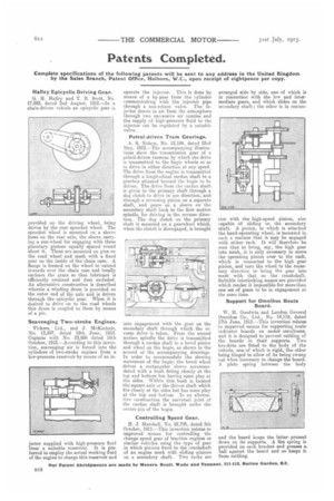
Controlling Speed Gear,
H. J. Marshall, No. 22,705, dated 6th October, 1912,—This invention relates to improved means for controlling the change speed gear of traction engines or similar vehicles using the type of gear in which pinions fixed to the crankshaft of an engine mesh with sliding pinions on a secondary shaft. Two racks are arranged side by side, one of which is in connection with the low and intermediate gears, and which slides on the secondary shaft ; the other is in connec
tion with the high-speed pinion, also capable of sliding on the secondary shaft. A pinion, to which is attached the hand-operating wheel, is mounted in such a manner that it may be engaged with either rack. It will therefore be seen that to bring, say, the high gear into mesh, it is only necessary to move the operating pinion over to the rack, which is connected to the high gear pinion, and turn the wheel in the necessary direction to bring the. gear into. mesh with that on the crankshaft. Suitable interlocking means are provided which render it impossible for more than one set of gears to be in engagement at. thesame time.
Support for Omnibus Route Board.
W. H. Goodwin and London General Omnibus Co., LW., No. 14,119, dated 17th June, 1912.—This invention relates. to improved means for supporting route indicator boards on motor omnibuses, and it is designed to prevent rattling of the boards in their supports. Two. brackets are fitted to the body of the vehicle, one of which is rigid, the other being hinged to allow of its being swung out when necessary to change the board. A plate spring between the body
and the board keeps the latter pressed, down on its supports. A flat spring is provided on each bracket and presses a. ball against the board and so keeps it_ from rattling.