


Clutches in Series
Page 66
If you've noticed an error in this article please click here to report it so we can fix it.
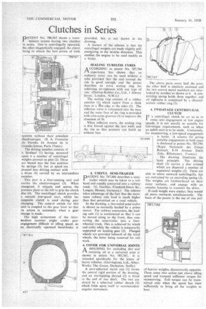
PATENT No. 788,367 shows a transmission system having two clutches in series. One is centrifugally operated, the other magnetically engaged, the object being to obtain the best points of both
systems without their attendant disadvantages. (S. A. Francaise du Ferodo, 64 Avenue de la (irande-Armee, Paris 17eme.) The driving member consists of a flywheel (1) having mounted upon it a number of centrifugal weights pivoted on pins (2). These are biased into the free position by springs (3), but at speed are pressed into driving contact with a drum (4) carried by an intermediate member.
This part is a free-running unit and carries the , electro-magnet (5). When energized, it attracts and moves the pressure plate to the left to grip the clutch disc (6). The centrifugal clutch provides a smooth low-speed start, whilst the magnetic clutch is used during gear changing. The control switch for this unit is coupled to the gear lever so that its action is automatic when a gear change is made.
The high momentum of the intermediate member might render gear engagement difficult at idling speed, so an electrically operated band-brake is provided; this is not shown in the drawing.
A feature of the scheme is that the centrifugal weights are made slightly selfenergizing in the reverse direction. This enables the engine to be used readily as a brake.
SEALING TUBELESS TYRES A CCORDING to patent No. 787,784 1-t experience has shown that an ordinary cover can be used without a tube provided that the seal around the rim is good enough, and the patent describes an extra scaling ring for achieving air-tightness with any type of rim. (Dunlop Rubber Co., Ltd., 1 Albany Street, London, N.W.1.)
The sealing ring consists of a rubber annulus (11 which tapers from a thick base to a Olin edge at the sides (2). The inflation valve is vulcanized into the base and the outer face of the ring is provided with criss-cross grooves (3) to improve the closeness of fit.
When inflation starts, the sealing ring is first forced against the tyre walls and the rim so that pressure can build up without loss.
A USEFUL SEMI-TRAILER PATENT No. 787,886 describes a semitrailer which may be taken to a railhead and rapidly converted into a railway truck. (G. Gaebler, Friedrich-Ebert Str., Langen, Hessen, Germany.) The scheme takes advantage of the fact that the maximum railway axle load is much higher than that permitted on a road vehicle.
In the drawing, a two-axled semi-trailer is shown as normally hauled by a prime mover. For railway conversion, the lead, ing axle (1) is constructed so that it can be moved along to the front, thus converting the semi-trailer into a fourwheeled truck. This is achieved by winch and cable while the vehicle is temporarily supported on landing gear (2). Flanged wheels are provided inboard of the tyred wheels, the latter being removed for rail work.
A COVER FOR UNIVERSAL JOINTS
I—I A HOUSING for excluding dirt and retaining oil in a universal joint is shown in patent No. 787.767. It is intended specifically for the joints of heavy vehicles. (Garringtons, Ltd.. Albert Works, The Green, Darlaston, Staffs.) A part-spherical metal cup (1) forms the central rigid portion of the housing. and an overlapping shroud (2) is fitted to the end of one shaft. The two are closed by a spherical rubber sheath (3) which folds upon itself to accommodate angular movement. The above parts cover half the joint; the other half is similarly enclosed and the two central metal members are interlocked by notches as shown at 4. A constricting spring holds them together, and oil tightness is completed by a channelsection rubber ring (5).
A TWO-STAGE CENTRIFUGAL CLUTCH
I F a centrifugal clutch be set so as to come into engagement at low engine speeds, it is not usually so suitable for full-torque requirements, such as when an uphill start is to be made. Conversely, for manoeuvring, a low-speed engagement is better. A scheme for giving suitable engagement in both cases is disclosed in patent No. 787,799. (Rcgie Nationale des Usines Renault, 8-10 Avenue Emile Zola, Billancourt, France.)
The drawing illustrates the basic principle. The driving shaft (1) carries a disc around which are disposed a number of segmental weights (2). These are able o move outward centrifugally, but are restrained by an encircling spring (3).. The weights are friction-faced on their outer surfaces, and engage with an annular housing to transmit the drive.
If each weight were similar, they would all move outwards simultaneously. The basis of the patent is the use of one pair of heavier weights, diametrically opposite. These come into action just above idling speed and transmit sufficient torque for manceuvring. Full torque can be transmitted only when the speed has risen sufficiently to bring all the weights to bear.