


Vernier Device for Setting Injection-pump Elements
Page 34
If you've noticed an error in this article please click here to report it so we can fix it.
rE exact matching of the several outputs of a multi-cylinder injection pump is of great importance, 'and patent No. 529,813 shows an improved means for making the necessary adjustment. The patentee, is P. L'Orange, Stuttgart, Germany.
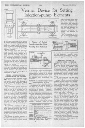
The drawing shows one unit of a pump according to4the invention. The inner rotatable sleeve emerges as a flange (5) on the outside, where it is fitted with an upstanding dowel-pin (4). A pinion (2) operated by the usual tack-bar is. also fitted with a dowel (1). Between the pinion and the flange is a coupling ring (3); this is differentially slotted on its two faces, the slots .fiting the two dowels,
To make an adjustment, the pinion is eased upwardly against its spring, and the ring (3) is turned the requisite number of notches. By virtue of the vernier principle, each notch gives an adjustment of 0.004 in.
TRULY CONSTANT-SPEED GOVERNOR FOR OIL ENGINES
AN injection-pump governor, claimed to eliminate the slight speed difference usually present after a change of load, is disclosed in patent No. 529,780 by F. Tippen., 21, Orchard Crescent, Coventry.
The centrifugal control mechanism consists of a loose-ball device (4) which slides the cup (3) to the right with an increase of speed. The sliding cup moves.a rod (5) which operates a slidevalve (6) in what is called the corrector unit. The valve (6)-controls the supply of pressure oil (from the lubricating system) to a piston (7) pivoted on a rocking-bar (2). The upper end of this bar is pivoted to the injection-pump rack-bar (1), whilst the lower end pivots on the rod (5) controlling the slide valve.
In operation, assuming a fall of engine speed due to load," the balls will move inwardly,. allowing the cup to
Move the rod (5) to the left. This• motion performs two functions, it rocks the lever (2) to operate the rack-bar (1), at the same time moving the slide. ,valve (6).
• Oilpressure is thereby presented to !..the,left face of 1h.e piston (7) and moves it to the right together with the fulcrum A.32
of the lever (2). Thus an excess adjustment is made to the rack-rod and the engine speed is restored to its original value instead of -a slightly lower speed. The centrifugal control then resumes its position, and recentralizes the slide-valve.
TORSION-BAR SUSPENSION WITH COMPENSATED ACTION
"TO ensure uniform load distribution, 1 irrespective of uneven ground, is the object of a design of torsion-bar suspension shown in patent No. 529,739 by, N. Salmon, " Trenance," Catherine goad, Surbiton. The scheme is also claimed to maintain an even keel over reasonable ground variations.
Whilst the drawing shows the scheme applied to a four-wheeled vehicle, it may be used with multi-wheelers, or even employed on track-layers.
Each wheel is attached by pairs *if pivoted " wishbone " links (1), one
IMPROVED HYDRAULIC INJECTION-PUMP GOVERNOR
FROM Bryce, Ltd., and H. Garrett, V both of Kelvin Works, Hackbridge, come, in patent No. 629,760, some improvements in hydraulic governing of injection pumps. The patent first describes the inherent defects of earlier systems, which usually consisted of a spring-loaded control plunger moved by oil pressure. from an engine-driven pump.
The chief objection has been that this scheme permits a wide range of " run-up," that is, the speed difference between no-load-and full-load settings. For example, an engine whose maximum loaded speed is 2,000 r.p.m. may be .permitted, by such a governor, lo race at 2,100 r.p.m., even allowing for the cutting down of the fuel. If adjustment be made to correct this, then 'the slow-speed response will overcorrect and cause " hunting."
An improvement to correct the above faults is illustrated. The rackrod (1) of the pump is moved by a plunger (2) which is subject to oil pressure from an engine-driven pump, the oil, being controlled by a valve attached to the accelerator. pedal. The irriprovement consists of the use of an extra plunger-controlled leak-off (3), which is also piped to the pedal-valve. At pedal-down positions, the leak (a) is closed, the system being adjusted to allow 5 per cent. " run-up." At Tow speeds, however, the pedal opens the leak (3), and the " run-up " may he 'increased to over 100 per cent., a value sufficient to prevent hunting.
The.pnent specification also includes graphs which more fully explain the action at various speeds.