


THE UPKEEP OF STEAM WAGONS.
Page 18
Page 19
If you've noticed an error in this article please click here to report it so we can fix it.
No. 12.— Overhaul and Repairs—Pump, Injector, Water Lifter, Water Heater, Transmission Gear and Driving Chains.
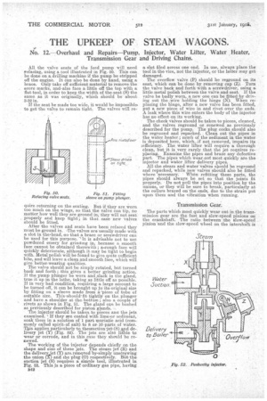
All the valve seats of the feed pump will need Sefacing, using a tool illustrated in Fig. 50. This can be done on a drilling machine if the pump be stripped off the engine. It can also be done by hand, using a brace. Only take off sufficient material to remove the score marks, and-also face a little off the top with a flat tool, in order to keep the width of the.seat (S) the same as it was originally, which should be about, 3-22 in.
If the seat be made too wide, it would be impossible. to get the valve to remain tight. The valves will re quire returning on the seating. But if they are worn too much on the wings, so that the valve can lip, no matter how well they are ground in; they will not seat , properly and keep tight ; in that case new valves should be fitted.
After the valves and seats have been refaced they must be ground in. The valves are usually made with a slot in the.headoso that a brace or screwdriver can be used for this purpose. "It is advisable not to use powdered emery for .grinding in, because a smooth face cannot be obtained therewith ; wough face will quickly deteriorate, although it may be tight to begin with. Metal polish will be found to give quite sufficient bite, and will leave a clean and smooth face, which will give better-wearing qualities. The valve should not be simply rotated, but turned back and forth ; this gives a better grinding action. If the _pump plunger be worn and,slack in the gland, true it up in the lathe, taking as little off as possible. If in very bad condition, requiring a large amount to be turned off, it can be brought up p3 its.original size by fitting on a sleeve made from a-piece of tube of suitable size. This 'should. fit tightly on the, plunger and have a shoulder at the. bottom ; also a couple of rivets as shown in Fig. 51. The gland can be bushed as previously described for piston glands. The injector should be taken, to pieces and the jets examined.. ' If they are coated with lirne,-or sediment, soak them in a solution of 1 part muriatic acid (commonly called spirit, of salt) to 8 or' 10 parts of water. This applies particularly to theisnetion 'jet (S) .and delivery jet (Y) (Fig. 52). The jets are also ligble to wear or corrode, and in this case they should be renewed.
The working of the injector depends chiefly on the shape and size of these jets. The steam jet (R) and the deliveryjet (Y) are.remqved brsimply unstrewing the union (T) and the plug (0) respectively. But the suction jet (8) requires a simple tool, illustrated in Fig. 53. This is a piece of ordinary gas pipe, having B42 a slot filed across one end. In use, always place the tool in the vice, not the injector, or the latter may get damaged. The overflow valve (P) should be reground on its seat, which can be done by removing cap (Z). Turn the valve back and forth with a screwdriver, using a little metal polish between the valve and seat. If the valve be badly worn, a new one can be fitted by driving out the .7ire holding the hinge (N). When replacing the hinge, after a new valve has been fitted, put a new piece of wire in and rivet over the ends. A leak where this wire enters the body of the injector has no effect on its working.
The cheek valves should be taken to pieces, cleaned, and the valves reground or. .renewed as previously described for the pump. The plug cocks should also be reground and -repacked. Clean out the pipes in the water -heater; much of the sediment in the water is deposited here, which, .if not removed, impairs its lefficiency. The water lifter will require a thorough clean, but it is very rarely that the jet requires replacing. Examine the pipes and braze any defective part. The pipes which wear out most quickly are the injector and water lifter delivery pipes. All the steam and water valves should be reground and repacked, while new valves should also be fitted where necessary. When refitting these parts, the pipes should always be set so that the joints fit properly. Do not pull the pipes into position by the unions, or they will be sure to break, particularly at the collars brazed on the ends, due to the strain put upon them and the vibration when running.
Transmission Gear.
The parts which most quickly wear out in the transmission gear are the fast and slow-speed pinions on the crankshaft. The ratio between the slow-speed pinion and the slow-speed wheel on the intershaft is usually about 1 to 7, which means that the teeth on the pinion will wear seven times as quickly as the teeth on the interwheel. The teeth are also liable to get damaged through carelessness when _changing gears, or a small part dropping between the gears, such as a loose nut or a stone thrown up by rubbertyred wheels. Broken teeth can be repaired by welding up with oxy-acetylene and filing out to a template made from the other teeth in the wheel or pinion. Another defect which sometimes occurs is a cracked intershaft wheel. This ca,n very rarely be satisfactorily repaired by either welding or patching, for the ,pitch line of the teeth is almost sure to be put out of _ truth. The best way is to fit a new wheel.
If the change-speed gear forks and spindles are . . slack, true out the holes in the bracket and fit new
1 1 i
forks and spindles. Too much play in these parts causes very objectionable rattling, and also increases the wear on the gear teeth. The chain pinion and wheel should run a considerable time before renewing, if the chain is kept in good condition, but the compensating pinions and spindles wear out much more quickly and require renewing more often. The compensating centre may require a new bush, for it is important that this should not get so slack that it can tip. This would put uneven strain on the compensating gear teeth, throw the chain sprockets out of line, and cause the teeth to cut into the side plates of the chain. The pressure would be concentrated at one end of the rollers and might crack them. The driving chain should be examined to ascertain if any links are worn or cracked. If a. chain breaks when on the road it often causes further damage, such as a broken spring or radius rod. Chains are also liable to stretch and may require shortening by removing one or more links.
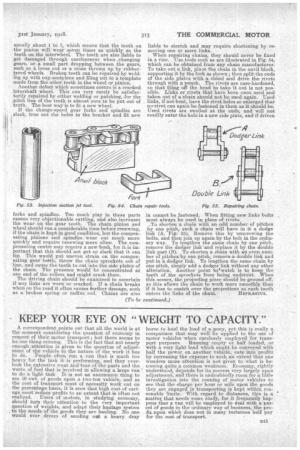
When repairing chains, they should never be. fixed in a vice. Use tools such as are illustrated in Fig. 54, which can be obtained from any chain manufacturer. To take out a link, place the chain in the anvil block, supporting it by the fork as shown ; then split the ends of the side plates with.a chisel and drive the rivets through with a punch. The rivets are case-hardened, so that filing off the head to take it out is not possible. Links or rivets that have been once used and taken out of a chain should not be used again. Used links, if not bent, have the rivet holes so enlarged that no rivet can again be fastened in them as it should be. Used rivets are swelled at the ends, and will not readily enter the hole in a new side plate, and if driven
in cannot be fastened. When fitting new links bolts must always be used in place of rivets. To shorten a chain with an odd number of pitches by one pitch, such a chain will have in it a dodge link (A, Fig. 55). Remove this by unscrewing the bolts, and then join up again by the bolt in the ordinary way. To lengthen the same chain by one pitch, remove the dodger link and replace it by the double link part (B). To shorten a chain with an even number of pitches by one pitch, remove. a double link and put in a dodger link. To lengthen the same chain by one pitch, simply add a dodger link without any other alteration. Another point to.watch is to keep the teeth of the sprockets from being undercut. When this occurs, the projecting piece should be ground off, as this allows the chain to work more smoothly than if it has to snatch over the projections as each tooth
enters the links of the chain. HEPE/ESTUS.