


"TRACTION BY PULL."
Page 16
Page 17
If you've noticed an error in this article please click here to report it so we can fix it.
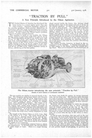
A New Principle Introduced by the Nilson Agrimotor.
TEElinited States of Ameriea has developed the farm tractor to a much higher point than any other country. American ingenuity, applied to the peculiar problems which present themselves in connection with this range of manufacturing activity, has produced many striking departures from accepted practice. In this respect the Nilson tractor presents features of rather unusual interest.
This machine is made in two models the Nilson . Senior, which is a powerful outfit with a 4f ins. by 61 ins. Waukesha engine, giving40 h.p. at 800 r.p.m. and 50 h.p. at 1200 r.p.m., and capable of dealing with four 14-in. bottom Ploughs in. all average soils. The
other, known as the Nilson Junior, is a three-plough
i , outfit, having a 4/ ins. by n ins. engine of the type
fitted to its bigger, brother, giving 30 bp. at 900 r.p.m. and 36 h.p. at 1200 r.p.m., with a drawbar rating of 16 h.p., and '25 h.p. atthe belt pulley.
The two models are similar in general details of design. The Kingston carburetter, fitted with Bennett air cleaner: is used, also the K.W. high-tension magneto with /repulse starter. Two speeds and reverse are furnished, using cut gears enclosed in oiltight cases, after automobile practice. The frame is of heavy channel iron-6 ins, in the Senior and 5 ins, in the Junior—and, unlike most tractors, mounted on semi.eiliptic oil-tempered springs With adjustable and equalizing features. In so far as the front wheels are concerned, the object of this arrangement obviously is to render the outfit more readily adaptable to road use.
The length of the Senior Nilson is 13 ft. 9 ins., that of the Junior 11 ft. 7 ins. The front wheels are 36 ins: and 32 ins., driving wheels 52 ins. and 50 ins., turning radius 17 ft. and 16 ft. respectively. Ready. for the land, the weight is 5900 lb. in the one ease and 4300 lb. M the other. The driver sits in front behind the engine as in a motorcar.
There are two outstanding original features about the construction. In the first place, the driving wheel is either single or triple. There is a single driving B38
wheel carried inside the frame, this driving , wheel having a 23-in. face in the larger and one of 18 ins, in the smaller machine. in this form the machine Can be used on firm ground. Two additional extension wheelimeasuring 10 ins. and 7 ins, wide in the two types of tintchinF--of the same size as the central driving wheel: are mounted on the outside of the frame, 'thus eying a fetal width of 43 ins: driving -wheel support in the one case and 32 inS, in the other. The front wheels are carried on an extended axle projecting beYond the wheel line of the rear wheel and its extensions, thus enabling one steering whecl to run in the furrow. and make the machine self-steering when ploughing.
_ The salient novelty, however, is found in the arrangement of the drawbar. A channel-steel arch, set at right angles to the frame, spans the central driving wheel. This arch is braced to the forward part of the frame, just abaft the engine, by strong tensional rods, one on either side. The drawbar takes the form of a pair of parallel arms hinged near the top of this arch and extending rearwards beyond the wheel and frame, and carrying a cross-member at their extremities thereby forming the drawbar.
Ifowever, this parallelogram, to which the ploughs are attached, and which is free to move vertically, upon its hinged supports at the top of the arch, straightens out-with the pull of the plough. Thus the pull of the work is taken not from the lower part of the frame as usual, but from the upper portion of the arch, on a level with the top of the wheel or thereabouts.
It will be seen, therefore, that any pull on the top of this arch, the arch itself being fixed at right angles to the frame, must tend to force the rear portion of the frame which carries the driving wheels downwards into closer contact with the ground. This forms the patent lever hitch, and according to the designer's contention the effect., is that, accordingly as the pull onthe ploughs increaseglay reason, of greater, stiffness of soil, greater depth of ploughing, or gradient, by,
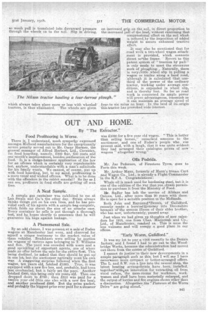
So much pull is translated into downward pressure through the wheels on to the soil. Slip its driving, which always takes place more or less 'with wheeled' tractors, is thus eliminated. The wheels are given an increased grip on the soil, in direct proportion to the increased pull of the load, without exercising that compressional effect on the soil, which induced,bYthe imposition of added 'weight to secure enhanced tractive effort.
It may also be mentioned that for road work a two-wheel wagon.attachment is provided, which connects direct tolthe frame. Resort to this patent system of "traction by pull" is only made to meet the strenuous work of ploughing:. Naturally, there is verytlittle wheel slip in pulling a wagon or trailer along a hard road, 'although it is calculated that onethird of the power of the ordinary tractor, working under average condition's, is expended . in wheel slip, and is thereby lost. So far as road work is concerned, its ample power will prove advantageous, inasmuch a.'s it can maintain an average .speed of founto six miles an hour. In the land of its.origin this-tractor has provoked wide interest.