


Dual Operation for Disc Brakes
Page 48
If you've noticed an error in this article please click here to report it so we can fix it.
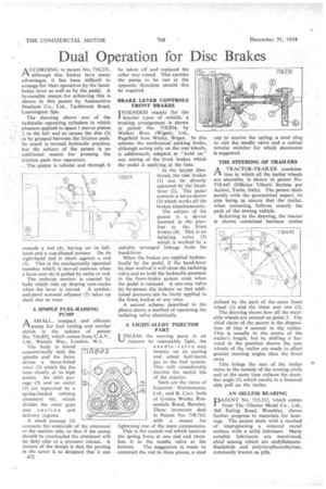
ACCORDING to patent No. 718,231, although disc brakes have many advantages, it has been difficult to arrange for their operation jy the handbrake lever as well as by the pedal. A favourable means for achieving this is shown in this patent by Automotive Products 'Co.,' Ltd., Tachbrook Road, Leamington Spa.
The drawing shows one of the hydraulic, operating cylinders in which pressUre applied to space! moves piston 2 to the left and so causes the disc (3) to be gripped between the friction pads. So much is normal hydraulic practice, but the subject of the patent is an additional means for pressing the friction pads into operation.
. The piston is tubular and through it extends a rod (4), having on its lefthand end a cup-shaped presser. On its right-hand end it abuts against a rod • (5). This is the mechanically operated member which is moved endwise when a lever arm (6) is pulled by cable or rod.
The endwise motion is created by balls which ride up sloping cam-tracks when the lever is moved. A ratchetand-pawl screwed adjuster (7) takes up slack due to wear.
A SIMPLE FUEL-RAISING • PUMP
rn.A SMALL, compact, and efficient pump for fuel raising and similar duties is the subject of patent No. 716,892, which comes from C.A.V., Ltd., Warple Way, London, W.3.
The body is bored concentrically with the spindle and the latter drives a three-lobed rotor (1) which fits the bore closely at its high points. An inlet passage (2) and an outlet (3) are separated by a spring-loaded rubbing abutment (4), which divides the rotor gaps into suction and delivery regions.
A small passage (5) connects the underside of the abutment to the suction side, so that if the pump should be overloaded the abutment will do duty also as a pressure release. A feature of the design is that the porting in the cover is so designed that it can
a22 be taken off and replaced the other way round. This enables the pump to be run in the opposite direction should this be required.
BRAKE LEVER CONTROLS -FRONT' BRAKES
INTENDED mainly for the .11. heavier types of vehicle, a braking arrangement is shown in patent No. 718,834, by Walker Bros. (Wigan), Ltd.,
Pagefied Iron Works, Wigan. In this scheme the mechanical parking brake, although acting only on the rear wheels, is additionally adapted tio " hold on" any setting of the front brakes which the .pedal is applying at the time.
In the layout Mils
(rated, the rear brakes (1) can be directly operated by the'handlever (2). The pedal controls a servo-motor (3) which works all the brakes simultaneously.
The subject of the patent is a device inserted in the pipeline to the front brakes (4). This is an isolating valve (5) which is worked by a suitably 'arranged linkage from the hand-lever.
When the brakes are applied hydraulically by the pedal, if the hand-lever be then worked it will close the isolating valve and so hold the hydraulic pressure in the front-brake system even when the pedal is released. A one-way valve (6) by-passes the isolator so that additiOnal pressure can be freely applied to the front. brakes at any time.
A second scheme described in the pltent shows a method of operating the isolating valve electrically.
• A LIGHT-ALLOY INJECTOR PART
UNLESS the moving parts in an injector be reasonably light, the needle-valve may bounce on its seating and admit half-burnt gas to the fuel system. This will considerably shorten the useful life of the injector.
Such are the views of Injection Maintenance, Ltd., and R. Carr, both of Gretna Works, Rossendale Road, Burnley. These inventors deal in Patent No. 718,762, with a means for lightening one of the main components.
This is the central rod which receives the spring force at one end and transfers it to the needle valve at the bottom. The suggestion is made to construct the rod in three pieces, a steel
cap to receive the spring, a steel plug to suit the, needle valve and a central tubular ineinber for which duralumin is suggested.
THE STEERING OF TRAILERS
r-V A TRACTOR-TRAILER "combination in which all the trailer wheels are steerable, is shown in patent No. 71-8,445 (Officine Viberti Societa per Azioni, Turin, Italy). The patent deals purely with the geometrical aspect, its aim being to ensure that the trailer, when cornering, follows exactly the path of the towing vehicle.
Referring to the drawing, the tractor is shown contained between circles defined by the path of the outer front wheel (1) and the inner rear one (2).
The drawing shows how all the steerable wheels are centred on point 3. The chief claim of the patent is the disposition of line 4 normal to the trailer. This is usually in the centre of the trailer's length, but by shifting it forward to the position shown the rear wheels of the trailer are made to effect greater steering angles than the front ones.
This brings the rear of the trailer more to the outside of the turning circle and at the same time reduces the drawbar angle (5) which results in a lessened side pull on the trailer.
AN OILLESS BEARING
DATENT No. 719,312, which comes
from The Glacier Metal Co., Ltd., 368 Ealing Road, Wembley, shows further progress in materials for bearings. The patent deals with a method of impregnating a sintered metal surface with a solid lubricant. Many suitable lubricants are mentioned, chief among which are molybdenumdisulphide and polytetrafluorethylene, commonly known as ptfe.