


A BUS THAT ALMO DRIVES ITSELF
Page 46
Page 47
Page 48
Page 51
If you've noticed an error in this article please click here to report it so we can fix it.
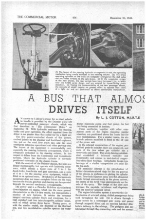
By L. J. COTTON, M.LR.T.E AN answer to a driver's prayer for an ideal vehicle to handle is provided by the Daimler CVD 650 power-controlled passenger chassis, which was first described in "The Commercial Motor" on September 24. With hydraulic assistance for steering, brake and gear operation, the effort required from the driver is no greater than that called for by a light car.
The first power-controlled chassis of this pattern, evolved jointly by the Daimler and Lockheed engineers. was put on the road four years ago, and has since undergone extensive operational and other proving tests. The layout of the equipment is commendably neat, especially the steering hydraulic arrangement, which is compactly embodied in the steering column. In this respect it differs from the Continental and transatlantic systems, where the hydraulic cylinder is normally positioned externally on the chassis frame.
With the controls of the Daimler chassis, the units are linked mechanically, but operate with hydraulic assistance, which affords a boost ratio of 3 to 1 for hand-brake, foot-brake and gear operation, and a ratio of 6 to 1 for the steering servo equipment, which is fitted as an optional extra. Breakdown of the hydraulic equipment does not mean complete failure on the road, because the brakes, gearbox and steering can be operated through the normal mechanical arrangements.
The power unit is a Daimler 10.6-litre six-cylindered direct-injection oil engine, which has the same general characteristics as the 8.6-litre model, but incorporates a number of new features. It retains the compact integral cast-iron cylinder block and crankcase, has a high camshaft and two interchangeable, cylinder heads, each of which covers three bores. Timing gears, as with the smaller model, are disposed at the flywheel end, and two parallel-drive spindles operate the water ;12 pump, hydraulic pump and fuel pump, the last two being connected in tandem.
These auxiliaries, together with other component parts of the engine requiring regular attention, are positioned above the frame line for easy maintainance. For a similar reason, the sixbranch exhaust manifold is fitted to the off side of the power unit.
In the internal construction of the engine, prefinished push-fit cylinder liners are employed, and each of the two valves per cylinder has a removable seat insert. The seven-bearing nitridedsteel crankshaft. is balanced statically and dynamically, and rotates in steel-backed copperlead-alloy-lined bearings. Detachable flange-type bearings of a similar composition are used for the big-ends.
Of particular interest is the introduction of Britest chromium-plated rings for the top grooves of the pistons, in preference to plating the cylinder liners. Four-hole injectors spray into flat, elongated bowls formed concentrically in the piston crowns, the centre of the bowl lying approximately on the axis of the spray. The design of the inlet port provides the requisite turbulence and dispenses with the need for screened valves.
The engine-lubrication system is noteworthy for the absence of external piping, drilled passageways being used throughout the unit. Oil is drawn through a gauze screen by a submerged gear pump and passed through magnetiC filters and an external full-flow filter before delivery to the oilways. The gudgeon pins are lubricated through the‘ connecting rods and the normal cylinder-wall lubrication is augmented by metered spray from a jet hole in the trailing shoulder of the rods.
Power from the engine is transmitted through an open-circuit Fluid Flywheel, in which the oil circulates through an oval vortex. Previously, the vortex was round and the driven members were equipped with an annular guide ring. This modification has had the effect of reducing the oil temperature and increasing the efficiency of the flywheel.
The drive between the flywheel, gearbox and rear axle is by propeller shafts with Hardy Spicer needleroller universal joints, the units being positioned in the frame to provide for constant-velocity motion of the transmission joints.
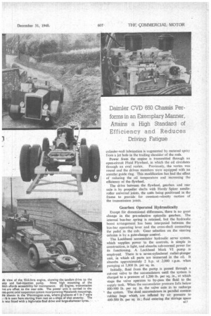
Gearbox Operated Hydraulically
Except fOr dimensional differences, there is no great change in the pre-selective epicyclic gearbox. The internal bus-bar spring is retained, but the hydraulic boost arrangement has been interposed between the bus-bar operating lever and the cross-shaft connecting the pedal in the cab. Gear selection on the steering column is by a gate-change control.
The Lockheed accumulator hydraulic servo system, which supplies power to the controls, is simple in construction, is light, and absorbs sub-normal power for its functioning. A Lockheed Mark VI pump is employed. There is -a seven-cylindered radial-plunger unit, in which all parts are immersed in the oil. It absorbs approximately 2 h.p. at 2.000 r.p.m. when pumping at 1,000 lb. per sq. in.
Initially, fluid from the pump is passed through a cut-out valve to the accumulators until the system is charged to a pressure of 1,200 lb. per sq. in., at which stage the valve operates to by-pass the fluid to the supply tank. When the accumulator pressure falls below 800-900 lb. per sq in. the valve cuts in to recharge the system. The dual accumulators in parallel contain rubber bags which, are inflated by air pressure to 400-500 lb. per sq in.; fluid entering the storage space is immediately subjected to air pressure, and a working pressure is created as soon as the pump starts to rotate.
Two independent systems are provided for brake operation. The master cylinder, connected to the rear brakes, is supplied with fluid from an inner compartment in the supply tank and the front brakes are coupled directly to the pump and a control valve. Should insufficient pressure be delivered by the pump— for example, when the engine stalls—application of the brake pedal will push a balance valve off its seating to expose the accumulator port and maintain the servo pressure.
If the Hydraulics Fail One of my tests with this chassis was to check its behaviour in the event of complete failure of the hydraulic system. I drove to a steep gradient, applied the hand brake, and stopped the engine. By operating the controls, the pressure in the accumulator was exhausted and the gauge connecting the system registered zero. The hand brake, because of its ratchet and mechanical linkage, held the vehicle on a ,1-in-7 incline without trace of creeping.
Steering and the gearbox operating pedal could still be worked, although slightly more effort was required than with a conventional chassis, because movement of the controls also required movement of the hydraulic system.
With the engine idling and in neutral gear, the accumulator pressure rose immediately to 500 lb. per sq. in. and continued to build up steadily to the maximum operating pressure in 3i mins. The system was again exhausted and the test repeated with the engine turning at governed speed. Maximum pressure was reached in 31 secs
Comparison of Effort
When driving with the gauge registering a reading of 500 lb. per sq. in.. the effort required to operate the controls was about the same as that needed for a normal chassis, and it decreased in relation to the pressure rise above this point.
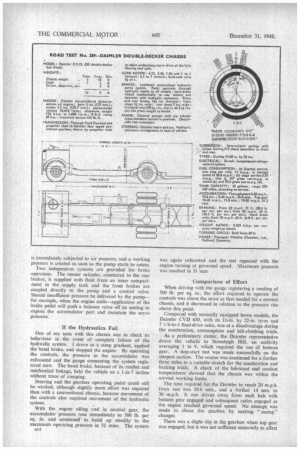
Compared with normally equipped home models, the Daimler CVD 650, with its 11-in. by 22-in. tyres and 5 1/6-to-1 final-drive ratio, was at a disadvantage during the acceleration, consumption and hill-climbing trials.
As a preliminary canter, the Daimler representative drove the vehicle to Stoneleigh Hill, an acclivity averaging 1 in 9, which required the use Of bottom gear. A stop-start test was made successfully on the steepest section. The course was continued for a further three miles to a suitable stretch for the acceleration and braking trials. A check of the lubricant and coolant temperatures showed that the chassis was within the normal working limits.
The time required for the Daimler to reach 20 m.p.h. from rest was 10.6 secs., and a further 14 secs. to 30 m.p.h. It was driven away from each halt with bottom gear engaged and subsequent ratios engaged as the engine reached governed speed. No attempt was made to abuse the gearbox by making "racing " changes.
There was a slight slip in the gearbox when top gear was engaged, but it was not sufficient materially to affect the results. In attempting to adjust the gear by pumping, I found that the pedal did not return with the alacrity associated with the mechanically operated preseiective gearbox. This controlled return of the pedal provides a smooth take-up in transmission.
Top-gear trials showed that the Daimler could aCcelerate from 10-20 m.p.h. in 12.8 secs., and to 30 m.p.h. in 31.2 secs. This performance emphasizes the comparatively high overall transmission ratio.
Effective. Braking Brake tests, made in the same area, convinced me that the Daimler had adequate retardation that was not marred by uneven pulling or fierceness. Employing the foot brake only, the chassis came to rest in 21 ft. from 20 m.p.h. and 48 ft. from 30 m.p.h. Because of the power assistance of the hand brake, the trials were extended to include a measurement when using that brake only. Readings taken from 20 m.p.h. produced a stopping distance of 63 ft.
Economy tests were made on the London road, and the. disparity in consumption between continuous running and stage-service operation again proved that the vehicle was geared for long-distance operation. To demonstrate the economy of the engine, the works representative drove at a steady 25 m.p.h. in top gear, and from a rolling start a distance of 1.6 miles was Covered before 0.1 gallon of fuel was exhausted.
Uthen changed places and drove the vehicle for the normal tests of one and four stops per mile. I accelerated from .each point, to governed engine revolutions. before engaging the next gear and braked fiercely at the stopping points. Is was established that a consumption equivalent to 5.75 m.p.g. on stage service and 12 m.p.g. in inter-urban service might be expected. Driving in a mare °economical manner, accelerating to 1,250 r.p.m. engine speed in each gear and observing a maximum speed of 25 m.p.h., the stage-service consumption was improved and a result equivalent to 7 m.p.g.was obtained.
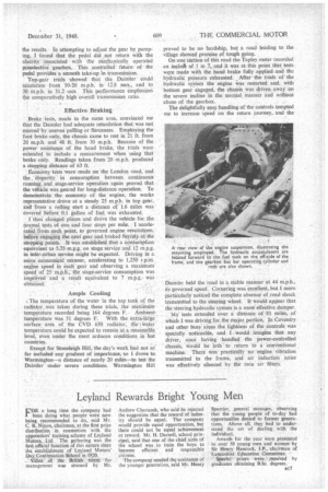
Ample Cooling The temperature of the water in the top tank of the radiator was taken during these trials, the Maximum• temperature recorded being 164 degrees F. Ambienttemperature was 51 degrees F. With the extra-large surface area of the CVD 650 radiator, the water temperature could be expected to remain at a reasonable level, even under the most arduous conditions in hot countries.
Except for Stoneleigh Hill, the day's work had not so far included any gradient of importance, so I drove to Warmington—a distance of nearly 20 miles—to test the Daimler under severe conditions. Warmington Hill proved to be no hardship, but a road leading to the village showed promise of tough going. .
On one section of this road the Tapley meter recorded an indult of I in 7, and it was at this point that tests were made with the hand brake fully applied and the hydraulic pressure exhausted. After the trials of the hydraulic system the engine was restarted and, with bottom gear engaged, the chassis was driven away on the severe incline in the normal manner and without abuse of the gearbox.
The delightfully easy handling of the controls tempted me to increase speed on the return journey, and the Daimler held the road in a stable manner at 44 m.p.h., its governed speed. Cornering was excellent, but I more particularly noticed the complete absence of road shock transmitted to the steering wheel. It would appear that the steering hydraulic system is a most effective damper.
My tests extended over a distance of 81 miles, of which I was driving for the major, portion, In Coventry, and other busy areas the lightness of the controls was specially noticeable, and I would imagine that any driver, once having 'handled the Power-controlled chassis, would be loth to return to a conventional machine. There waspractically -no 'engine vibration transmitted to the frame, and air induction noise was effectively silenced by the twin air filters.