


Patents Completed.
Page 22
If you've noticed an error in this article please click here to report it so we can fix it.
Complete specifications of the Icalowing patents will be sent to any address in the United Kingdom upon receipt of eightpence per copy at Sales Branch, Patent Office, Holborn, W.C.
BRAKES.—Hallot.—No. :11,863, dated 9th November, 1907.—This brake consists of a box or casing (141 keyed to the axle so as to rotate therewith and having a loose cone member (H. Mounted within the box are brake collars (49, 50) which are constantly forced into frictional contact with the loose cone member (1) by means of a cam (47) operated by a spring (48) through the lever (46). Also arranged within the casing (14) is a mass (13) which makes contact with the cone member (11
by centrifugal force. Surrounding the
cone member (1) are brake bands (4, 5) which are operated through suitable gear by the brake pedal, It will be seen that, when the pedal is depressed, the bands (4, 5) will hold the loose cone Member (1) stationary, and the braking force will be obtained by spring (48) and by the centrifugal action of the mass (13) which will vary according to the speed of the vehicle. An additional brake is also provided consisting of two coned clutch members (16, 15). The cone member (161 is carried by a spindle (18) which has a resilient connection with the brake-operating gear. This auxiliary brake is arranged to come into operation only when the brake pedal is depressed to its fullest extent.
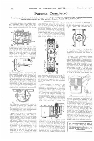
RESILIENT WIIE EL.—Stevens.—No. 9,274, dated 29th April, 1908.—This invention relates to vehicle wheels of the type in which a tire is carried by a rim supported by pneumatic or other cushioning means. The present improvement consists in providing a second pneumatic tube or other elastic cushion arranged upon the hub of the wheel. The hub (a) is provided with a groove adapted to accommodate a pneumatic tube (b). Two side plates are provided attached one to each side of the hub (a) and are bent outwardly as at d to receive the pneumatic or other elastic rings (e) upon which clamp plates (g) rest. The outer ends of these plates are secured to side rings (i) and with them carry the tire (h) which is of double-tread form. The side plates (c) are secured together by bolts (f) extending through openings (k) in the webs of the clamp plates (in. The plates (g) are bolted together and bent outwardly as at gl so as to fit over the pneumatic tube or other elastic ring (10. It will be seen that either of the plates (c) can be removed from the wheel without dismounting the latter, and if either or both of the pneumatic tubes (e) become deflated the wheel will be directly supported from the hub (a) by the plates (g) and the pneumatic tube (b).
CARBURETTER. — Adams. — No. 28,132, dated 27th December, 1907.—This carburetter comprises the usual float chamber (A) communicating by way of the channel (El with a spray nozzle (G) arranged within the carburetting chamber (13). This nozzle is provided with a series nt holes (J) of different diameter, and these are arranged to be uncovered or put in communication with the carburetting chamber. A rotary valve (II is provided, which acts as a combined throttle and air valve. This valve has a central boss
which rests upon and completely covers the holes (J) in the spray nozzle (G) except for an opening (Hi which is arranged to uncover either of the holes (J) according to the position of the valve. The arrangement is such that whea the throttle is nearly closed the smallest hole (J) in the spray nozzle (G) will register with the opening (111 and as the combined throttle and air valye is further opened a larger
hole will be uncovered in the nozzle (G In this way a correct mixture of fuel an air will be obtained at all speeds of B.. engine. When the combined air an
throttle valve is ful y opened, the fuel w) be completely cut off so that pure air drawn into the cylinder for cooling pu poses.
WATER TUBE 1.10ILERS.—Schmid —No. 3,756-1908, dated, under Conve: tion, 11th May, 1907.—This invention r latex to high-pressure steam generators 4 the water-tube type, having a forced ci culation. The boiler comprises two sy terns of tubes (a, b) arranged in serie The tubes (a), into which the feed wat4 is forced, are arranged in the top portic Of the boiler casing in the path of ti cooler gases, and the tubes (b) in the lowl portion or directly above the furnace ) as to be in the path of the hottest gase Water is forced past the feed check val (p) into the tubes (a), where it is part evaporated, and from thence the mixtu of saturated steam and water is convey by way of the pipe (n) to a steam dru or header (.0. From the drum (s) water is caused to flow through a pi (f) to a pump (r) which forces it at increased velocity through the seco system of tubes (b) and finally to t steam drum (s) by way of the pipe (I In another arrangement the pump (r) dispensed with and the feed water frc the tubs (a) is directed to an inject which forces the water in the drum through the second system of tubes several times at an increased velocity.