


IEREI
Page 122
If you've noticed an error in this article please click here to report it so we can fix it.
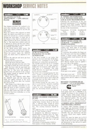
SERVICE This Bulletin describes the method to be used when checking and adjusting a Lipe single plate clutch as fitted to the E6 and ES6 trucks.
When the clutch is first adjusted on initial build, the clutch cross-shaft lever is positioned 18° forward of a vertical centreline through the cross-shaft. A centre dot at the bottom of the shaft is positioned one spline forward of the lever centreline (see Fig. 1). The clutch slave cylinder push rod is adjusted as shown and the wear indicator is positioned with the pointer opposite the INITIAL SETTING mark.
As the clutch driven plate wears, the cross shaft, rotates clockwise and the lever moves back towards the slave cylinder. When the pointer aligns the ADJUST mark, the clutch must be adjusted as follows: Remove the split pin and clevis pin from the lever and jaw.
Slacken the lever pinch bolt.
Knock the lever from the shaft.
Clean dirt and paint from the end of the cross-shaft to locate the centre pop mark.
Refit the lever with the pop mark two splines clockwise of the lever centreline (see Fig. 1). The lever will assume a position some 18" forward of the vertical. The pointer should be opposite the INITIAL SETTING mark.
When the wear indicator again aligns the ADJUST mark with the centre pop mark two splines forward of the lever centreline, the driven plate has reached the end of its life.
After fitting a new driven plate or complete clutch assembly, remember to respline the lever so that it assumes a position 18" forward of a vertical centreline with the shaft centre pop mark one spline forward of the lever centreline i.e. in the as new' position. It has been brought to our notice that operators who have had their AC5R alternators service exchanged to an AC5RS alternator are wiring them up incorrectly. The AC5RS alternator has its 'F' terminal bridged internally to the main negative making the brown/green cable which normally goes to it redundant. This cable should therefore be taped back securely as it is not now required.
The lower 3/8 in terminal having the sine wave— beside it should NOT he used to connect this cable to as this will then provide an intermittent direct short which will eventually burn out this cable, usually behind the instrument panel.
The terminal having the sine wave-beside it is provided for operators requiring a low speed cut-out, a drive to a rev. counter or some tachographs which require the alternating feature provided by it.
BRAKE CHAMBER STIFFENING PLATE
To improve the life to the Bendix Type 30 spring brake chamber fitted to the front axle, a stiffening plate should be fitted between the axle bracket and brake chamber. The existing fasteners should be used.
The stiffening plate is not required where the `K` Type chamber is fitted.
To distinguish the difference between a Bendix/Magnum chamber and a 'K' Type, observe the release bolt hexagon. The Bendix/Magnum type bolt has a hexagonal head whilst the 'K' Type has a nut and split pin arrangement.
Part number of stiffening plate 101655-4. Part number of brake chamber 45769.
`E' SERIES TRANSMISSION P.T.O. INSTALLATION KITS — 4106 & 6109 TRANSMISSIONS Following the introduction of the syn chromesh transmission, P.T.O. installatiot kits have been made available. The kit: enabled the Z.F. P.T.O.'s to be fitted b the rear of the transmissions.
Transmission P. T. 0.Kit Installation Ki Type Pt. No. Pt. No.
Eaton 4106 106333-5 107967-0 Eaton6109 106537-5 107968-6 Prior to Engine First ESN 44338091 som engines may show signs of oil ieakag from the flange/gasket area of the fror gear cover_ To overcome this problem the flange pre file of the gear cover has been modified t include a raised section which provide increased gasket crush between the sett crew holes.
When fitting a new cover, a thin film ( HIV Silicone Sealant must be applied t the cover side of the gasket.
Front gear cover — old type prior to ES]
44338091 Pt.No. 391164 Front gear cover — new type after ESN 44338090 Pt.No. 391619 Front gear cover gasket — asbestos free
Pt.No. 391343 Front gear cover seal Pt.No. 390813 The revised front gear cover is a produt improvement and not subject to Campaig Change.
A revised 'seven grommeted' cylindt head gasket Part No. C 3882568 is no available for fitment to the Cummins LI engine. Engines which require head ga ket replacement should be fitted with tl new, improved gasket. The new gaski was first fitted to engine Serial Ni 23521806 and is a product improvement.
CUMMINS 6BTA THERMOSTAT AND HOUSING CHANGE
In August 1988 Cummins changed ti single jiggle pin thermostat 3912587 at its housing 3903756 to a new double jigg pin thermostat 3914408 and housit 3914409. The new thermostat and hou ing were fitted from engine numbe 21030774.
Great care must be taken not to fit tl incorrect thermostat into a housing esp cially in the case of the new double jigs pin thermostat as this will not fit square in the old housing.