


Progress in Trailer-brake Design
Page 54
If you've noticed an error in this article please click here to report it so we can fix it.
ACCORDING to patent No. 413,435, by Harrier Motors, Ltd., R. F. Clayton and R. Dean-Avems, of Huddersfield, the problem of actuating trailer brakes is often complicated by the fact that a particular tractor may be required to be coupled up to one of several trailers, each of which would most likely differ from the others in the matter of brake-facing wear. This means that the degree, of braking would not be evenly distributed over all the running wheels, unless some method of compensation were employed. A compensated system has, however, the drawback that, in the event of the tractor being used on its own, the braking system is left with an " open end," in other words, the movement is lost in an effort to pull on the non-existent trailer brakes.
The object of this invention is to provide a compensated system which can be converted by a simple handlever movement into a self-contained mechanism for solo work.
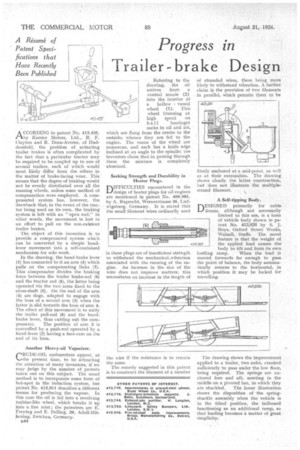
In the drawing, the hand-brake lever (1) has connected to it an arm (4) which pulls on the compensating links (7). This cOrnpensator divides the braking force between the trailer brake-rod (6) and the tractor rod (8), the latter being operated via the two arms fixed to the cross-shaft (5). On the end of the arm (4) are dogs, adapted to engage with the boss of a second arm (3) when the latter is. slid towards the boss of arrn 4. The effect of this movement is to unify the trailer pull-rod (8) and the handbrake lever, thus cutting out the com
pensator, The position of arm 3 is controlled by a push-rod operated by a hand-lever (2) having a face-cam on the end of its boss.
Another Heavy-oil Vaporizer. 1--,RUDE-011, carburetters appear, at ‘......the present time, to be attracting the attention of many inventors, if we may judge by the number of patents taken out on this subject. The usual method is to incorporate some form of hot-spot in the induction system, but patent No. 413,911 describes a different means for producing the vapour. In this case the oil is fed into a revolving turbine-like wheel, which breaks it up into a fine mist; the patentees are E. Freytag and E. Delling, 26, Adolf-Hitlerring, Zwickau, Germany.
B44 Referring to the drawing, the oil arrives from a central nozzle (2) into the interior of a hollow vaned wheel (1). This wheel (running at high speed on b a 11 bearings) sucks in oil and air, which are flung from the centre to the outside; whence they are fed to the engine. The vanes of the wheel are numerous, and each has a knife edge inclined at an angle to the spindle; toe inventors claim that in .passing through these the mixture is completely atomized.
Seeking Strength and Durability in Heater Plug.3.
plIFFICULTIES encountered in the
design of heater plugs for oil engines are mentioned in patent No. 409,985, by A. Ruprecht, Wernerstrasse 35, Ludwigsburg, Germany. It is stated that the small filament wires ordinarily used in these plugs are of insufficient strength to withstand the mechanical-vibration associated with the running of the engine. An increase in the siile of the wire does not improve matters; this necessitates an increase in the length of the wire it the resistance is to remain the same.
The remedy suggested in this patent is to construct the filament of a number of stranded wires, these being more likely to withstand vibration. A further claim is the provision of two filaments in parallel, which permits them to be
firmly anchored at a mid-point, as will as at their extremities. The drawing shows clearly the latter construction, but does not illustrate the multiple. strand filament.
A Self-tipping Body. DESIGNED primarily for cable L./drums, although not necessarily limited to this use, is a form of vehicle body shown in patent No. 413,826 by S. J. Boys, Oxford Street Works, Walsall, Staffs. The novel feature is that the weight of 409,955 jthe applied load causes the body to tilt and form its own
loatling ramp. When the load is moved forwards far enough to pass the point of balance, the body automatically returns to the horizontal, in which position it may be locked for travelling.
The drawing shows the improvement applied to a trailer, two axles, cranked sufficiently to pass under the low floor, being required. The springs are anchored fore and aft, meeting in the middle on a pivoted bar, to which they
are shackled. The lower illustration shows the disposition of the springshackle assembly when the vehicle is in the tilted position, the tailboard functioning as an additional ramp, so that loading becomes a matter of great