


A NOVEL CHAIN-DRIVEN SIX-WHEELER.
Page 59
Page 60
If you've noticed an error in this article please click here to report it so we can fix it.
First Published Details of the Latest Rigid-frame Six-wheeled Caledon.
pits latest form the Caledon six-wheeler •differs conderably from the original type, and the layout of the four-wheeled bogie, the rear springing and the chain drive are partieularly interesting and unlike anything which we have seen heretofore.
The chassis is of most substantial construction, and its power -unit is a 40-50 h-p., with four cylinders of 5-in, bore and 6i-in. stroke. The cylinders are cast en bloc and have detachable heads and ample water-jacket space, which is provided with baffles in order to secure complete circulation of the cooling water around each valve and cylinder. The
inlet and exhaust-valve operating mechanism is enclosed in oil and dustproof covers. For lubrication, oil is forced to all the bearings through the crankshaft, which is drilled and constructed of high-tensile steel. The cylinder walls are, as usual, lubricated by splash. The maximum speed of the engine is controlled by an efficient form of governor.
For cooling, the water is circulated through the jackets and radiator by a pump, the cooling being assisted by a fan. The radiator itself is of the built-up type, with castaluminium header and bottom tank, which are ribbed to assist radiation and to give a good appearance. The vertical tubes are provided with gills.
The drive is taken through an internal cone clutch and thence via a fairly long clutchshaft, with two fabric flexible joints to a Dux patent gearbox in which all the forward gears are constantly in mesh, the various ratios being secured by the employment of clutches having internal teeth. With this type of box, engagement of the gears is extremely simple and positive, and there is no risk of stripping or chipping the teeth of the pinions, as sometimes happens in the more ordinary form of gearbox. Four gpeeds forward and a
reverse are provided, the corresponding speeds at normal engine revolutions being: 4, 8, 11 and 16 m.p.h., with a reverse of 4 m.p.h.
Immediately behind the gearbox is a wide brake drum with fabric-lined shoes. This brake is operated by foot.
As the wheelbase is fairly long, it has been found advisable to embody a two-piece propeller .shaft, with a centre bearing and three fabric flexible joints.
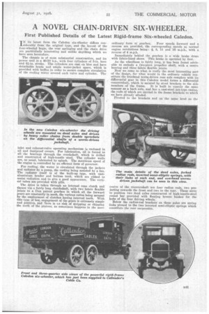
Now we come to what is really the-most interesting part of the design, foe what would in the ordinary vehicle constitute the overhead worm-driven rear axle complete with its differential gear in this Caledon model forms a differential countershaft, which is secured by stout brackets to the side
members of the frame. It is built in exactly the same manner as a back axle, and has a east-steel pot-type casing. the ends of which are carried in the frame brackets to which we have already alluded.
Pivoted to the brackets and on the same level as the centre of the countershaft are four radius rods, two projecting towards the front and two to the rear. These serve to position two dead axles constructed of high-tensile-steel round bar provided with floating bronze bushes for the hubs of the four driving wheels.
Below the radius-rod brackets on these axles are spring links pinned to the two inverted semi-elliptic springs which constitute the rear suspension. At the ends of the countershaft are mounted two double sprocket wheels, and, from these, short roller chains convey the drive to the front and rear bogie wheels, so that in one pair of chains the tension is in the upper portions, whilst in the other it is in the lower.
All the wheels are of the hollow cast-steel spoked type, equipped with 41-in, solid rubber tyres, singles at the front and twins at the rear.
Steering is by -worm and Segment gear in an oil and dustproof case, and secured to an easily detachable bracket mounted on the top of the frame.
The front axle itself is a forging with heavy nickel-steel stub axles. Phosphor-bronze floating bushes are also employed in the front-wheel hubs.
We have not yet referred to the brakes on the bogie wheels. These are operated through a compensating bar, at each end of which is a smaller compensator for the driving ,wheels at its side. The whole layout appears to afford a most satisfactory degree of accessibility and it is easy to remove the casing ccutaining the final drive and differential gearing.
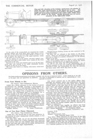
As will be seen from one of our illustrations, one of the first examples of this new model has been purchased by Callender' s Cable and Construction Co., Ltd., for carrying the heavy loads with which they have to deal.