


A NEW STEAM VALVE.
Page 28
If you've noticed an error in this article please click here to report it so we can fix it.
A Résumé of Recently Published. Patents.
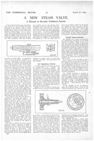
A new and interesting type of distribution valve for a steam wagon has been patented by E. Atkinson and J. Sadler (evidently of the Preston company of the former name, makers of the well-known Atkinson steam wagon). It is a rotary valve, and would appear to have advantages in respect of the range of cut off which is possible when it iv used. It is so simple, in regard to both its construction and operation, that the briefest
.2es.oription should suffice. A cylindrical valve is in two parts, divided by a partition which splits it up into two half cylinders. One end of each half cylinder is blanked up, and the two blanked ends are at the opposite ends of the valve. Ports are cut in the wall of each half. Each port is different in length; measured round the circumference, as compared with the others, but each is wide enough to serve as an admission port or exhaust port for the engine cylinder. By sliding the valve along in its chamber, different ports are brought into use, and in that manner provision is made for, the different ratios of cut off. The one part of the valve serves for exhaust, and the other for steam. It is slid along in its chamber by means of a rod controlled by the driver from his cab. Steam enters the valve at one of the open ends, and passes thence to the cylinder when the port which is in use _comes opposite to the port in the wall of the engine cylinder. As the valve rotates the other side of it comes to face the cylinder wall, and one of the ports at that side releeses the exhaust steam which passes out at the open end of that half of the valve. An auxiliary valve may be etilized to provide for reversing the engine. A small slide valve is -used, which, in one extreme position, puts, say, the righthand end of the main valve in commurrication with the steam supply, and the left-hand end in communication with the atmosphere. By pushing this auxiliary -valve to the oppeisite+end of its chamber the right-hand end of the main valve is connected to the, atmosphere, instead of, as before, with the steam supply1 and the opposite end is in communication with the steam supply instead of, as before, with the atmosphere. What were previously the-steam ports ofethe valve now become exhaust ports, and what were exhaust ports become eteem. and in -consequence the working of the engine is `reversed.
The valve is driven by bevel gearing from the engine crankshaft through a coupling, which is designed to allow of the position of the valve being adjusted during erection, or afterwards. The valve, in order to allow of its being moved longitudinally for the purpose of bringing into use the various ports, rides B34
on p, feather key on the driving shaft. The main valve only requires to be controlled by hind from the cab, a floating connection between the main and reversing valve providing for the manipulation of the latter. It will be gathered that the movement of the hand lever is practically the same as that of the ordinary .reversing lever in the case of a slide valve gear, with the addition of extra notches for linking up. The one main valve is
designed to supply steam to two I igh pressure cylinders. The specification is No. 147,376.
An Ingenious Clutch.
A rather ingenious clutch is described in_ specification No. 147,274, by R. Schmitz, an American citizen. He claims for it That it is self-centring, and .therefore not likely to give trouble owing to faulty alignment, that the rotative action of the mechanism always tends to prevent its disengagement, thus avoiding the necessity for a heavy spring, that when engaged it is practically impossible for this clutch to slip, yet at the same time, when it is disengaged, 'it absolutely releases, and quickly separates from the other member. Finally, he claims that it takes hold very gradually, and cannot in any circumstances seize.
Briefly, it may be said to consist of a number of shoes, shaped on their outsides to conform to the inside of the flywheel. They are pivoted eccentrically to the flywheel itself, and when disengaged lie' snugly together at a considerable distance away from the inner\ surface of that flywheel. Movement of the clutch pedal in the orthodox fashion thrusts forward a hollow sleeve, on the inner rfare of which is cut a quick thread screw. This engages with another on e. hub which is mounted on the clutch shaft. The hollow sleeve is prevented from rotating, so that its longitudinal movement, under the influence of the clutch pedal, causes the inner one to rotate, which, by the means of a system of levers and pins, throws the shoes out into contact with the interior of tho flywheel. The actual rotation of the clutch always, on account of centrifugal force, keeps the clutch in: good contact, so that a light spring only is necessary to keep the clutch engaged.
Detail Improvements.
No. r47,275, by j. Dixon, provides for the independent springing of the front wheels of a vehicle. Each wheel is carried on a. stub axle which is supported from the frame by a pair of parallel rods. The opposite corners of the parallelogram so formed are joined by a spring designed equally to resist compression or extension. No axle is needed, in the ordinary sense of the word, so that height may be saved. There afe nioaffications described, and the invention appears to be particlelady applicable. to a three-wheeled machine in which the rear driver is a single wheel.
H. N. Moore, in No. 147,384, by interpeeing a simple two-speed gear hetweei the gearbox and final drive of a Ford car, increases the number of changes of speed obtainable by 100 per cent., and also provides a neutral gear, by the use of.which, as he states, the difficulty sometimes met with of being unable to start the engine owing to the sticking of the clutch is eliminated.
No. 147,381. describes a method of enriching the mixture by introducing, with the usual extra air, a small proportion of paraffin,, which is drawn from a box belted to the exhaust manifold. The inventor ela,ims considerable fuel economy to reseal, from the adoption of his device. The patentee is J. H.
In No, 135,270, by W. B. Robeson, extra air is drawn from a muff on the exhaust manifold and injected into the induction pipe through a fine gauze. The method is stated to improve the carburation of the mixture.
No. 133,672 describes a rather complicated looking coupling, for use between tractor and trailer, by the use of which the connection is, although tight, always flexible, whether the tractor be pulling or whether the trailer be overrunning, and therefore pressing on the back of the tractor. The same resilience is still main tamed when the tractor is higher ot lower than the trailer. The patentees are C. Michel and A. Dime.