


Electrical Hardening Without Distortion
Page 62
If you've noticed an error in this article please click here to report it so we can fix it.
A ReS11111 of Patent Spedfications that Have Recently Been Published, T1Edevice shown in patent No. 4190,514 has for its object the quantity production of thin-walled components, such as wheel hubs and brake drums, the interior surface of which it is desired to harden without causing distortion. This patent comes from H. Somes, 1049, Yorkshire Road, Grosse Point Park, Mich., U.S.A.
The drawing shows the apparatus with a work-piece (a hub) (I) in
position on the heating unit. The latter consists of a helical conductor (2) mounted upon a highly permeable iron core (3), the work-piece being a close fit on the outer face of the helix, Thus is formed a transformer in which the inner surface of the huh constitutes a short-circuited secondary winding ; when high-frequency current is applied to the coil the skin of the bore is instantly made red hot, only to be quenched by the proximity of the cold hulk of the metal.
The helical conductor is hollow, and is water-cooled; this is necessary in view of the high frequency used—some 2,500 cycles per second. A magnetic field of this frequency tends to heat any conducting mass placed in it.
Servo Hydraulic Braking.
I MPROVEMENTS in the design of hydraulic servo brakes are disclosed in patent No. 413,0,793, by L. Renault, 8, Avenue Emile Zola, Rillancourt, France. The scheme, as a whole, has
been covered by several earlier patents, and the present one is concerned purely with an a.dvantageous form of construction.
The driver's pedal (I) operates, via a cable, a lever (6) pivoted on a cross shaft. This lever controls a powerdriven, friction-clutch servo motor (not shown), which amplifies the driver's effort and turns a cam (2) through part of a revolution. The cam operates the master cylinder of the hydraulic system via a compression bar (3).
In order to provide, also for direct mechanical operation of the cylinder, the linked levers (4 and 5) form an alternative system; this, of course, is not amplified by the servo motor.
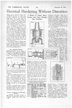
Pressure Accumulator for Hydraulic Systems.
ASCHEME for powerstorage, to ensure the immediate operation of hydraulic brakes and other corn848
ponents, is discloed in patent No. 490,450, by E. Rockwell, 110, Norwood Road, West Hartford, Conn., U.S.A.
The system employs a gear pump driven by an electric motor, the circuit of which is automatically opened and closed in accordance with the pressure
in the hydraulic accumulator. Tracing the fluid circuit, oil arrives at the inlet ((I) and traverses an annular, sheet-metal filter (5), the interior of which houses the switch gear. The oil emerges on the left of the filter and passes, via a passage (8), to the motordriven gear pump, indicated generally at 9.
The pump inflates the cylindrical space (3), which is bounded, by a stationary cup-washer (left) and a moving one (right). The latter is carded on a piston rod (7). which operates the motor switch ; this is shown in broken line, as also are the loading springs (4). High-pressure oil is taken from the port (2), whilst the dome (1) contains a small quantity of air for cushioning purposes.
The claims are based chiefly on the form of construction rather than on the main Principle.
Control of Injection Pumps.
AN injection pump, disclosed in patent No. 490,547, makes use of a novel means for varying the commencement of injection, this being controlled hydraulically. The patentee is La Precision Mecanique, 11, rue Vergniaud, Paris.
In this design the plunger is fitted with a pair of helical edges (7), which regulate the output by rotation of the plunger through the medium of a rackbar (2), so much being standard prac
tice. The plunger, however, is not operated directly, but derives its oscillating motion from a secondary plunger (4) operated in the usual way from the camshaft. An intermediate space (6) is filled with fuel, which acts as a solid abutment (after the port (5) has been passed) and transmits the motion to the
plunger proper. A second port (3), however, permits a further slight leakage, which can be made -proportional to time by means of a calibrated orifice or a spring-loaded valve (I). The ultimate effect is to permit of greater leakage at low speeds than at high speeds, and so an automatic advance effect is produced.
This seems an ingenious method of dispensing with the conventional advance-and-retard mechanism, which is of a somewhat complex nature.