


UNLOADING AND LOADING EQUIPMENT.
Page 30
If you've noticed an error in this article please click here to report it so we can fix it.
A Résumé of Recently Published Patent Specifications.
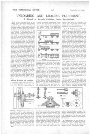
There is more than one device on the market which facilitates rapid loading or unloading of a motor vehicle, and utilizes for that purpose a more or less stationary trailer, or alrailer which may be moved by means other than mechanical power; the aim of all of .them being the limitation of the idle time of the motor vehicle. The principal object of patent No. 131,157', by James Dalziel and others appears to,be that of overcoming one of the outstanding difficulties with most such devices, in that a considerable time has to be spent in adjusting the m6tor vehicle and trailer so as to' ensure correct alignment of one with the other. This correct alignment is essential owing to the fact that as a rule the load is transferred from -the motor vehicle to trolley and vice versa on a platform fitted with rollers and running on rails. This patentee' surmounts the -difficulty by carrying the rails on the trailer or. if necessary, on the motor vehicle, on a framework which is on rollers, and capable of being moved transversely over the surface of the terry,or trailer as the case may be, for short distances. Involuntary movement is restrained by means ',of chains and. Wheels. When, for example, a load is about to he delivered by. the motor vehicle, it is backed up to the trolley ; the frame carryingfrthe rails on the trolley is then pulled to one side or the other until the rails thereon are in alignment with those on the motor vehicle. The two sets of -rails are then coupled by means of telescopic lengths of rails provided for -the purpose,. and the load is hauled on or off by means of a
winch and tope. Suitable means are provided for preventing endwise movement of the load on the motor lorry or on the tuolley, once it has -been rim into place.
Other Patents of Interest.
The design of hub and stub axle for a front steering wheel, which is the subject of No. 131,205 is particularly in
it a pin to take the front portion of the joint of the longitudinal steering rod. In one piece with the sleeve is formed a boss which is secured to the usual vertical steering pivot.. The advantages claimed are facility for spacing the wheel bearings widely widely apart and providing a suitable reservoir for the oil. The patentees are W. J. Thomas and E. G. Wrigley and Co,, Ltd.
Specification No. 131,228 describes a new form of shackle pin foe which it is claimed that 'it is an improvement on others in respect of the means afforded for lubrication a the pin. Two methods. of carrying this invention into effect are illustrated and described. In one, a fairly long central portion of the, shackle pin is turned to a less diameter than the main body of the pin. Into the centre of this reduced portion opens.the usual hole leading to the central passage for grease. A groove is cut along the bearing surface of the pin, and opens into this reduced portion at each end of it.
shackle and helps to distribute the grease, and also prevents closure of the supply hole. The patentees are the Streatham Engineering Co., Ltd.
Mr. J. W. Docherty, in his differential mechanism, which he .describes in No. 130,860, eliminates all internal toothed gears. The central star piece, instead of being fitted wit& differential. pinions, has formed upon its sides, duplicate inclines facing in opposite directions, and these engage with similar inclines or wedge-shaped faces on circular-driving discs. The, backs of these discs are Corrugated, and the corrugations mesh with similar faces on portions keyed to the end of' the live axle shafts. A certain amount of movement of the intermediate wedge-faced discs is possible in the direction of the axis of the driven shafts, and
this is restrained by springs. When one wheel overruns the other, the driving-disc-onthat,side slips out of mesh against4thesresistauce of the spring. The provision of suitable stops brought into action by coming into contact with the wedge-shaped faces of the driving discs prevents both of them from being disengaged at one time.
No. 130,865 describes an arrangement for utilizing acetylene 'gas with. hydro carbons, such as paraffin vapour. A tank is divided into two by a partition of wick-like substance held together by wire gauze. Paraffin and a'oetylene,gas -enter at tone side. a-nd are intermingled in the course of their passage 'through the-wicks. They emerge at, the far side, and are thence dravn by the engine into the induction pipe. The patentee is J. Hawthorne.
In the magneto coupling which has been invented by T. R: Heyworth, and described in No.' 130,933, one portion of the coupling drives its shaft only through the medium of a small central spur wheel with which.i. it engages through the
teresting. A long sleeve, designed to ac-1 commodate ball or roller airings at each end, carries within these ball bearings.a spindle to the outer end of which the road whel is secured, the wheel being so disposed that the line of the load falls almost centrally with the principal roller bearing. The main portion of the spindle and the sleeve which encloses it projects inwards towards the centre of the vehicle. It is fitted with a cap which, on one wheel only, has formed integral with
B54 It is claimed that by this means stoppage of the hole leading from the 'centre of the pin to the bearing 'surface is rendered much less likely to happen, as a coating of grease is formed round the pin at this part which keeps away any dirt which might otherwise choke the nle. jn the other arrangement a split sleeve encircles the pin where the central portion is cut away. This sleeve, owing to the movement of the shackle pin within its bearing, moves round and round upon the, medium of projecting keys or pegs. Provision is made for sliding this half of the coupling on the shaft so as to release -it from engagement with this spur wheel, and thus allow of adjusting the timing of the magneto.
G. Constantinesco, in No. 131,020, describes a valveless oil pump for internalcombustion engines, which utilizes the inertia of a column of oil within the pump to obviate the need for valves.