


Selective Tandem-axle Drive I
Page 80
If you've noticed an error in this article please click here to report it so we can fix it.
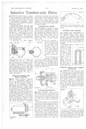
PATENT No. 820,103 shows a tandem" axle arrangement in which both axles are driven at low road speeds, but as the speed rises the drive to one of the axles is automatically disengaged. (Eaton Axles, Ltd., Victoria Road, Great Sankey, Warrington, Lancs.) The drawing shows the two axle assemblies connected by a propeller shaft fixed to the two flanges (1). The main power input member is the spider (2) which drives the bevel pinion of the leading axle. It also drives, via a spur gear (3), a gear (4) journalled freely on the rear-drive spindle. The reversal of direction created can be corrected either by an idler pinion or by a reversed bevel in the rearmost axle.
A dog-clutch (5), when engaged.
couples the spur gear to its shaft and establishes the rear drive. The clutch can be operated by a sliding fork (6). The fork is worked by an electric motor (7) which is controlled by a centrifugal switch responsive to road speed, high speed causing disengagement. The patent gives details of the electrical mechanism and shows the circuit used. An overriding control permits the driver to operate the clutch.
EXHAUST BRAKING FOR BLOWN ENGINES WHEN exhaust braking is employed W on a supercharged engine, the blower is throttled when the obturator is in use. The back pressure resulting is harmful for the supercharger, causing high temperatures and vibration. Patent No. 818,559 describe% a simPle method of preventing this. (Daimler-Benz A.G.. Stuttgart-Untertiirkheim, Germany.) Referring to the drawing, the mechanically driven blower (1) supplies air to the inlet manifold, whilst the throttle for the exhaust is shown at 2. The exhaust throttle is couped to a flap-valve by-pass (3) on the induction system, so that when the throttle closes the valve opens. The relative proportions of movement
are important; the flap valve must move slowly at first and then increase its speed, with respect to the movement of the throttle. The exhaust throttle is also connected to the accelerator and clutch pedals so that power and braking cannot' be applied together.
CENTRIFUGAL FILTER
ACENTRIFUGE detailed in patent No. 817,978 is designed as a lubricating oil filter. Mounted on the end of the crankshaft, the separator works at a high peripheral speed but the rate of oil flow is small, giving ample time for thorough cleansing. (Fiat Societe per Azioni, 200 Corso Giovanni Agnelli. Turin, Italy.)
In the drawing, the crankshaft is shown carrying a vaned rotor (I). The oil from the gear-pump enters through a groove (2) and passes along the annular space between a bore in the crankshaft and a central tube (3). It enters the vane chamber via cross-bores (4).
As the centrifuge turns impurities congregate at the largest diameter and flow over the edge of the rotor and through a perforated diaphragm (5). The solids stay at this point while the oil flows radially inwards to re-enter the crankshaft system through the central tube.
WATER COOLED drum brakes, W detailed in patent No. 819,947, are said to overcome the problems of local over-heating and distortion often found with such systems. (Roy S. Sanford and Co., and others, Seymour, Connecticut, U.S.A.).
The brake shown is of conventional form, but the friction material consists of metal having a high conductivity, such as electrolytic copper or even silver. The inner surface of the facing has grooves cut in it; these run circumferentially so that, when it is attached to the shoe, the grooves form a series of small channels.
These are the water jackets, the water being forcibly pumped through them by a positive-type pump. The water enters at the point 1 and leaves via a pipe con
nection (2) to reach the other shoe. The water is drawn from the engine cooling system.
IGNITION COIL COOLING
AN ignition coil incorporating aircooling passages is shown in patent No. 818,205. (Auto Union Berlin G.m.b.H., Am Juliusturm 42-46, Berlin Spandau, Germany.) Two types of zoil are described; one has cooling passages around the outside of the windings and the other has them between the two windings.
The drawing shows a section of the second type. The secondary winding (1) is in the centre and an air space separates it from the primary winding (2). Between the primary winding and the outer case is another air space. Bottom vents (3) and others (4) at the top permit a through flow of air.
FORK-LIFT TRUCK FOR NARROW GANGWAYS
A FORK-LIFT truck with the forks "Th mounted at the side to facilitate work in narrow gangways, is shown in .patents Nos. 820,781 and 820,782. (G. links, Cleco Works, Foundry Square, Leicester.) A general layout is shown in the drawing. The chassis frame is substantially U-shaped in plan and is provided with four wheels which can be steered in unison. Two of the wheels can be raised or lowered slightly, always in opposition to each other, to compensate for surface rregularities.