


A Hydraulic Transmission System
Page 58
If you've noticed an error in this article please click here to report it so we can fix it.
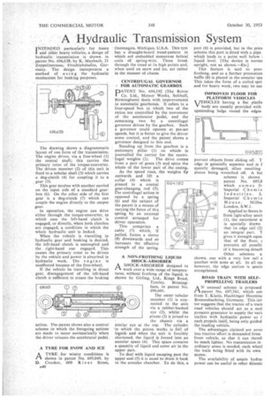
INTENDED particularly for buses and nther heavy vehicles, a design of hydraulic transmission is shown in patent No. 696,638, by K. Maybach, 21 Zeppelinstrasse, Friedrichshafen, Germany. Thedesign incorporates a method of using the hydraulic mechanism for braking purposes.
The drawing shows a diagrammatic layout of one form of the transmission. The engine drives, via a free-wheel (I) the central shaft; this carries the primary rotor of the torque-converter. The driven member (2) of this unit is fixed to a tubular shaft (3) which carries a dog-clutch (4) for coupling it to a gear (5).
This gear meshes with another carried on the input side of a standard gearbox (6). On the other side of the first gear is a dog-clutch (7) which can couple the engine directly to the output gear.
In operation, the engine can drive either through the torque-converter, in which case the left-hand clutch is engaged, or directly, when both clutches are engaged, a condition in which the whole hydraulic unit is locked.
When the vehicle is travelling in hydraulic gear and braking is desired, the left-hand clutch is uncoupled and the right-hand one engaged. This causes the primary rotor to be driven by the vehicle and power is absorbed in hydraulic work. The engine is unaffected because of the free-wheel.
If the vehicle be travelling in direct gear, disengagement of the left-hand clutch is sufficient to create the braking action. The patent shows also a control scheme in which the foregoing actions are made to occur automatically when the driver releases the accelerator pedal.
A TYRE FOR SNOW AND ICE
riA TYRE for wintry conditions is shown in patent No. 695,049, by D. Crooker, 600 River Street, A40
Ontonagon, Michigan, U.S.A. This tyre has a draught-hoard tread-pattern in which are embedded numerous helical coils of spring-wire. These break through the tread at its high points and, when used on snow and ice, act rather in the manner of chains.
CENTRIFUGAL GOVERNOR gFOR AUTOMATIC GEARBOX
PATENT No. 694,192 (The Rover Co. Lid., Meteor Works, Solihull, Birmingham) deals with improvements in automatic gearboxes. It refers to a four-speed box in which two of the ratios are controlled by the movement of the accelerator pedal, and the remaining two by a centrifugal governor driven by the gearbox. Such a governor could operate at pre-set speeds, but it is better to give the driver some control, and the patent shows a governor designed to this end.
Standing up from the gearbox is a stationary pillar (1) on whichis journalled the carrier for the centri fugal 'weights (2). The drive comes frcim •a pair of gears (3) and.spins the whole of the lower part of the casing.
As the speed rises, the weights fly outwards and lift a collar (4) which is pinned to a central gear-changing rod (5). The centrifugal action is opposed by a spring (6) and the subject of the patent is a means of varying the force of this spring by an external control arranged for driver operation.
This comprises a cable (7) which, if pulled, forces a sleeve (8) downwards and so increases the effective strength of the spring.
A NON-FROTHING LIQUID SHOCK-ABSORBER
I–I A SHOCK-ABSORBER designed to
work over a wide range of temperatures, without frothing of the liquid, is shown by Girling, Ltd., Kings Road, Tyseley, Birmingham, in patent No. 696,601.
The outer tubular member (1) is connected to the axle via a rubber-bushed eye (2), whilst the piston (3) is joined to the chassis via a similar eye at the top. The cylinder in which the piston works is full of liquidr and when the unit is forcibly shortened, the liquid is forced into an annular space (4). This space contains a quantity of liquid and some air in the upper part.
To deal with liquid escaping past the upper seal (5) it is usual to drain it back to the annular chamber. To do this, a port (6) is provided, but in the presi scheme this port is fitted with a pipe which leads to a point well below I liquid level. [The device is norma upright, not as shown.—EDJ This feature is said to prey. frothing, and as a further precaution baflle (8) is placed in the annular spa This takes the form of a coiled spri and for heavy work, two may be use IMPROVED FLOOR FOR PLATFORM VEHICLES
VEHICLES having a flat platfo body are usually provided with upstanding ledge round the edges
prevent objects from sliding off. T edge is generally separate and is f quently damaged, often resulting pieces being wrenched off. A bet scheme is shown patent No. 695,8 which comes fr. Imperial Chem i c Industries, L Imperial Chemic House, Millba London, S.W.1.
Applied to floors bi from light-alloy sectig (1), the outermost st is specially drawn that its edge rail (2) an integral part. T gives it strength equal that of the floor, 2 prevents all possibi of it becoming detach Other schemes a shown, one with a very low rail a another with none at all. In all cm however, the edge section is specia strengthened.
ROAD TRAIN WITH SELFPROPELLING TRAILERS A N unusual scheme is proposed patent No. 697,541, which con from T. Klatte, Huchtinger Heerstrai Bremenhuchting, Germany. This inv tor suggests that the tractor of a train road vehicles should act as a mot pressure generator to supply the varig trailers with hydraulic power so t each propels itself, being only guided the leading vehicle.
The advantages claimed are sever less tractive effort is demanded from front vehicle, so that it can theref. be much lighter. No transmission in ordinary sense is needed, each wheel the train being fitted with its own motor.
The availability of ample hydra" power can be useful in other directic