


Tyre That Can Be Run Deflated
Page 36
If you've noticed an error in this article please click here to report it so we can fix it.
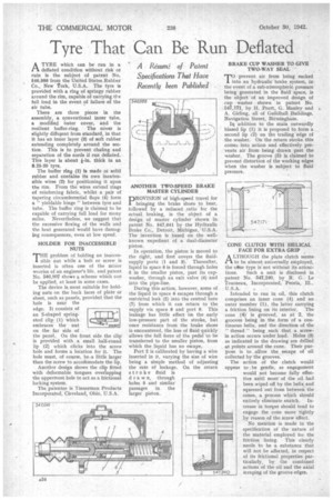
ATYRE which can be run in a deflated condition without risk ot ruin is the subject of patent No. 546,986 from the United States Rubber Co., New fork, U.S.A. The tyre is provided with a ring of springy rubber around the rim, capable of carrying the full load in the event of failure of the air tube.
There are three pieces in the assembly, a conventional inner tube, a modified imter cover, and the resilient buffer-ring. The cover is slightly diffeEent from standard, in that It has an inner layer (3) of soft rubber extending completely around the section. This is to prevent chafing and separation of the cords if run deflated. This layer is about fin, thick in an 8.25-20 tyre.
The buffer ring (1) is made 01 solid rubber and contains its own inextensible wires (2). for positioning it upon the rim. From the wires extend rings of reinforcing fabric, whilst a pair of tapering circumferential flaps (4) form a " yieldable hinge" between tyre and tube. The buffer ring is claimed to be capable of carrying full load for many miles. Nevertheless, we suggest that the excessive flexing of the walls and the heat generated would have damaging consequences, even at low speed.
HOLDER FOR INACCESSIBLE NUTS
THE problem of holding an inaccessible nut while a bolt or screw is inserted is often one of the minor worries of an engineer's life, and patent No. 546,807 shows a scheme which can be applied, at least in some cases.
The device is most suitable for holding nuts on the back faces of plate or sheet, such as panels, provided that the hole is near the edge. It consists of an S-shaped springsteel clip (1) which embraces the nut on the far side of • the panel._ On the front side the clip" is provided with a small half-round lip (2) which clicks into the screw hole and forms a location for it. The hole must, of course, be-a little larger than the screw to accoMmodate the lip.
Another design shows the clip fitted with deformable tongues overlapping the uppermost hole to act as a frictional locking system.
The patentee is Tinnerman Products Incorporated, Cleveland, Ohio, U.S.A. DROVISION of high-speed travel for 1 bringing the brake shoes to bear, followed by a reduced ratio for the actual braking, is the object of a design of master cylinder shown in patent No. 547,041 by the Hydraulic Brake Co., Detroit, Michigan, U.S.A. The invention is based on the wellknown expedient of a dual-diameter piston.
In operation, the piston is moved to the right, and first covers the fluidsupply ports (1 and 3). Thereafter, liquid in space 6 is forced through holes 5 in the smaller piston, past its cupwasher, through an exit valve (4) and into the pipe-line.
During this action, however, some of the liquid in space 6 escapes through a restricted leak (2) into the central bore (7) from which it can return to the supply via space 8 and port 9. This leakage has little effect on the early low-pressure part of the stroke, but once resistance from the brake shoes is encountered, the loss of fluid quickly allows the full force of the pedal' to be transferred to the smaller piston, from which the liquid has no escape.
Port 2 is calibrated by having a wire inserted in it, varying the size of wire being a simple method of adjusting the rate of leakage. On the return stroke fluid is draw n, through holes 5 and similar passages in the larger piston. prevent air from being sucked 1into an hydraulic brake system, in the event of a sub-atmospheric pressure being generated in the fluid space, is the object ' of an improved design of cup washer shown in patent No. 547,171, by H. Pratt, G. Manley and A. Girling, all of Guildhall Buildings, Navigation Street, Birmingham.
In addition to the main outwardly biased lip (1) it is proposed to form a second lip (2) on the trailing edge of the washer. On the return stroke this comes into action and effectively prevents air from being drawn past the washer. The groove (3) is claimed to prevent distortion of the working edges when the washer is subject to fluid pressure.
CONE CLUTCH WITH HELICAL FACE FOR EXTRA GRIP
A LTHOUGH the plate clutch seems to be almost universally employed, the cdPrie type is not without its attrac tions. Such a unit is disclosed in patent No. 547,240, by R. G. Le Tourneau, Incorporated, Peoria, III., U.S.A.
Intended to run in oil, this clutch comprises an inner cone (4) and an outer member (1), the latter carrying
a friction lining on its interior. The cone (4) is grooved, as at 2, the grooves being in the form of a continuous helix, and the direction of the " thread " being such that a screwin action occurs under load. Holes (9) as indicated in the drawing are drilled at points around the cone. Their purpose is to .allow the escape of oil collected by the grooves.
The action of the clutch would appear to be gentle, as engagement would not become fully effective until most of the oil had been wiped off by the helix. and squeezed out from between the cones, a process which should entirely eliminate snatch. Increase in torque should tend to engage the cone more tightly by reason of the screw effect.
No mention is made in the specification of the nature of the material employed for the friction lining. This clearly needs to he a substance that will not be affected, in respect of its frictional properties particularly, by the combined actions of the oil and the axial scraping of the groove edges.