


ELECTRIC VEHICLE CHASSIS IMPROVEMENT.
Page 36
If you've noticed an error in this article please click here to report it so we can fix it.
A Resume of Recently Published Patents.
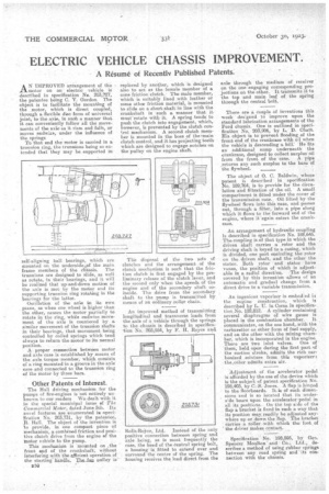
AN IMPROVED arrangement of the motor on an electric vehicle is described in specification Ne. 203,727, the patentee being C. V. Gordon. The object is to facilitate the mounting of the motor, which is direct coupled, through a flexible disc form of universal joint, to the axle, in such a manner that it can conveniently follow all the movements of the axle as it rises and falls, or moves endwiae, under the influence of the springs
To that end the motor is carried in a trunnion ring, the trunnions being so extended that they may be supported in self-aligning ball bearings, which are mounted on the underside of the main frame members of the chassis. The trunnions are designed to slide as well as rotate, in their bearings, and it will be realized that up-and-down motion of the axle is met by the motor and its supporting trunnion ring rotating in the bearings for the latter.
-Oscillation of the axle in its own plane, as when one wheel is higher than the other, causes the motor partially to rotate in the ring, while endwise movement of the axle is countered by a similar movement of the trunnion shafts in their bearings, that movement being controlled by coiled springs which tend always to return the-motor to its normal
position. .• • A proper connection between motor and axle case is established by means of the axle torque member, which consists of a ring mounted in a, groove in the axle ease and connected to the trunnion ring of the motor by three bars.
. Other Patents of Intevest.
The Hall driving mechanism for the pumps of fire-engines is not entirely unknown to our readers We dealt with it in the special municipal issue of The Commercial Motor, dated June 5th. Its novel features are enumerated in specification No. 203,731, by the patentee, rt. Hall. The object of the invention is
• to provide, in one compact piece of mechanism, a combined friction and positive clutch drive from the engine of the Motor vehicle to the pump. .
This mechanism is 'mounted on the front end of the crankshaft; without interfering with there.fficient operation of the starting handles The,—fan pulley is B50 replaced by another, which is designed also to act as the female member of a cone friction clutch. The male member, which is suitably lined with leather or some other friction material, is mounted to slide on a short shaft in line with the crankshaft in such a manner that, it must'rotate with it. A spring tends to 'Nish the clutch into engagement, which, however, is prevented by the clutch control mechanism. A second clutch member is mounted in the boss of the+main clutch control, and it has projecting teeth which are designed to engage -notches on the pulley on the engine shaft. • The disposal of the two sets of clutches and the arrangement . of the clutch mechanism is such that the friction clutch is first engaged by the preliminary release of the clutch lever, and the second only when the-speeds of the engine and of the secondary shaft coincide. The drive from the secondary shaft to the pump is transmitted by means of an ordinary.roller chain.
An improved method of transmitting longitudinal and transverse loads from the axle of a vehicle through the springs to the chassis is described in specification No. 203,954, by F. H. Royce and, Rolls-Royee, Ltd.. Instead of the only positive connection between spring and axle being, as is most frequently the case, the head of the Central spring bolt, a housing • is fitted to extend over and surround the centre of the spring. The housing receives the load direct from the axle through the medium of receiver on the one engaging corresponding projections on the other. It transmits it to the top and main leaf of the spring through the central bolt.
There are a couple of inventions this week designed to improve upon the standard lubrication arrangements of the Ford chassis. One is outlined in specification No. 203,906, by L. D. Chatt. His object is to prevent flooding of the 'front end of the crankcase with oil when the vehicle is descending a hill: He fits an additional sump underneath the crankcase, designed to collect surplus oil from the front of the case. A pipe ,returns any such surplus to the base of the flywheel.
The object of 0. C. Baldwin, whose patent is described in specification No. 189,764, is to provide for the circulation and filtration of the oil. A small compartment is fitted under the cover of the transmission case. Oil lifted by the flywheel flows into this ease, and passes out, through a filter, into a pipe along which it flows to the forward end of the engine, where it again enters the crank
ORS&
An arrangement of hydraulic coupling is described in specification No. 188,645. The coupling is of that type in which the driven shaft carries a rotor and the driving shaft is keyed to a easing, which is divided, one part encircling the rotor on the driven shaft, and the other the stator. Both rotor and stator have vanes, the position of which is adjustable in a radial direction. .The design covered by this invention allows of an automatic and gradual change from a direct drive to a variable transmission.
An ingenious vaporizer is embodied in the engine construction, which is described by L. U. la Corsa in specifica-, tion No. 182,812. A cylinder containing several diaphragms of wire gauze is placed in the combustion chamber. It communicates, on the one hand, _with the carburetter or other form of fuel supply, and on the other with the mixing -chamber, which is incorporated in•the engine. There are two inlet valves. One of them, held open during the first part of the suction stroke, admits the rich carbonized mixture from this vaporizer: the,other -admits extra air.
Adjustment of the accelerator pedal is afforded by the use of the device which is the subject of patent specification No, 198,403, by C.-S. Jones. A flap is hinged to the floorboards. It.is of such dimensions and is so located that its undersde bears upon the accelerator,pedal in all its positions. On the top side of the flap a bracket is fixed in such a way that its position may readily he adjusted anywhere up or down the flap. The bracket• carries a roller with which the foot of the driver makes contact.
Specification No. 198,595, by Geo. Spencer Moulton and Co., Ltd., describes a method of using rubber springs between any road spring and' its cennection with the chassis.