


A ROTARY VALVE ENGINE.
Page 70
If you've noticed an error in this article please click here to report it so we can fix it.
A Résumé of Recently Published Patent Specifications.
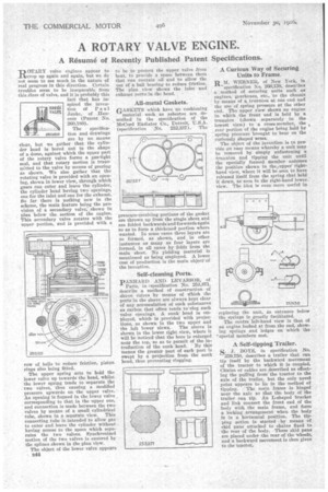
lapp OTARY valve engines appear to ..Ltscrop up again and again, but we do not seem to see much in the nature of real progress in this direction. Certain troubles seem to be inseparable from this Class of valve, and it is probably this fact that has inspired the invention of Paul Janke, of Hanover (Patent No. 2(10,180).
The specification and drawings are by no means clear, but we gather that the cylinder head is bored out tp the shape of a dome, against which the upper part of the rotary valve forms a gas-tight seal, and that rotary motion is transmitted to the valve by means of gearing as shown. We also gather that the rotating valve is provided with an opening, shown in lower view, through which eases can enter and leave the cylinder, he cylinder head having two openings, one for the inlet and one for the exhaust. So far there is nothing new in the scheme, the main feature being the provision of a secondary valve, shown in plan below the section of the engine. This secondary valve rotates with the upper portion, and is provided with a
row of balls to reduce friction, piston rings also being fitted. The upper spring acts to hold the lower valve up towards the head, whilst the lower spring tends to separate the two valves, thus causing a modified pressure upwards On the upper valve. An opening is formed in the lower valve corresponding to that in the upper one, and connection is made between the two valves by means of a small cylindrical tube, shown in a separate view. This connecting tube is intended to allow gas to enter and leave the cylinder without having access to the space which separates the two valves. Synchronized motion of the two valves is ensured by the splines shown in the plan view.
The object of the lower valve appears to be to protect the upper valve from heat, to provide a space between them that can contain oil and to allow the use of a ball bearing to reduce friction. The plan view shows the inlet and exhaust ports in the head.
All-metal Gaskets.
GASKETS which have no cushioning material such as asbestos are described in the specification of the McCord Radiator Co., Detroit, (specification No. 252,337). The pressure-reeeivilg portions of the gasket are thrown up from the single sheet and are folded backwards and forwards again so as to form a thickened portion where wanted. In some cases three layers are so formed, as shown, and in other instances as many as four layers are formed, in all cases by folds from the main sheet. No yielding material is mentioned as being employed. A lower cost of production is the main objectsof the invention.
Self-cleaning Ports.
pANHARD AND LEVASSOR, of
Paris, in ospecification No. 253,871, describe a method of construction of sleeve valves by means of Which the ports in the sleeve are always kept clear of any accumulation of such substances as carbon that often tends to clog such valve openings. A sunk bead is employed, which is -provided with projections, as shown in the two upper and the left lower views. The eleeve is shown in the lower right view, where it will be noticed that the bore is enlarged near the top, so as to permit of the introduction of the snnk head. By this means the greater part of each port is swept by a projection from the sunk head, thus preventing clogging.
A Curious Way of Securing Units to Frame.
RM. WERNER, of New York, in
'specification No. 260,138, describes a method of securing units such as engines, gearboxes, etc., to the chassis by means of a trunnion cit one end and the use of spring pressure at the other end. The upper view shows an engine in which the front end is held by a trunnion (shown separately in the lowest view) to a cross-member, the rear portion of the engine being held by spring pressure brought to bear on the curiously shaped arms. The object of the invention is to provide an easy means whereby a unit may be removed by simply unfastening a trunnion and tipping the unit until the specially formed member asthimes the position shown in theupper righthand view, where it will he seen to have released itself from the spring that held it down, as seen in the right-hand lower view. The idea is even more useful in replacing the unit, as entrance below the springs is greatly facilitated. The centre left-hand • view is that of an engine looked at from the end, showing springs and ledges on which the 'special members rest.
A Self-tipping Trailer.
S. J. BOYS, in specification No. 259,750, describes a trailer that can tip itself by the backward movement of the tractor to which it is coupled. Chains or cables are described as effecting the pulling from the tractor to the axle of the trailer, but the only novel point appears to lie in the method of tipping. The main frame is hinged near the axle so that th'e body of the trailer can tip. An L-shaped bracket and link connect the front end of the body with the main frame, and form a )(Kling arrangement when the body is in a horizontal position. The tipping action is started -by means of skid pane attached to chains fixed to the rear of the body. These skid pans are placed under the rear of the wheels, and a backward movement is then given to the tractor.