Patents Completed.
Page 20

If you've noticed an error in this article please click here to report it so we can fix it.
Four-wheel Drive Construction. A New Carburetter. Brake Bands. An Improved Resilient Wheel.
Copies of complete specifications of the patents published on this page can be obtained from the Sales Branch, Patent Office, Holborn, WC, at the cost of sixpence for each specification.
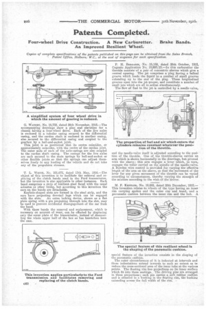
G. WeanEv, No. 16,732, dated 26th November, 1915.—The accompanying drawings show a plan and elevation for a cha.ssis having a four-wheel drive. Each of the live axles is enclosed in a tubular casing secured to the differential casing, and the cardan shaft is enclosed in another easing, also secured to the differential casing and coupled to the gearbox by a ball-and-socket joint.
This joint is so positioned that its centre coincides, Or approximately coincides, with the centre of the cardan joint. The outer ends of each of the axle-casings are also coupled to the cardan shaft casing. The casings for the live axles are each secured to the main springs by ball-and-socket or other flexible joints 60 that the springs can adjust themselves freely to any loading of the vehicle and do not take any of the propulsion stresses.
T, L. WarrE, No. 101,672, dated 13th May, 1916.—The object of this invention is to facilitate the removal and replacing of the clutch bands used in the Ford transmission, but the invention is also applicable in other instances. Each band comprises a strip of resilient steel faced with the usual asbestos or other lining, but according to this invention the ears on the bands are detachable.
Keyhole-shaped slots are formed in the steel strip, and the ears 'have projecting dovetail lugs which can be engaged with the slots. An extra locking device, shown as a fiat plate spring with a pin projecting through into the slot, may be used to prevent accidental disengagement of the ear from the band.
With these bands the removal and replacement, which is necessary on account of wear, can be effected by displacing only the cover plate of the transmission, instead of dismantling the whole upper half of the box as has heretofore been the case.
P. H. BERGASSE., No. 15,139, dated 26th October, 1915, Cognate Application No. 15,993/15.—In this carburetter the throttle consists of a pair of concentric sleeves which give a central opening. The jet comprises a plug having a helical groove which feeds the liquid to a number of small grooves extending up to the end of the plug. These longitudinal grooves open into the jet 'proper, and constitute a number, of small jets which are all in action simultaneously.
The flow of fuel to the jet is controlled by a needle-valve, and the needle-valve itself is adjusted according to the position of the throttle. One of the throttle-sleeves carries an arm which is shown horizontally in the drawings, but pivoted with the sleeve; this arm engages a lever which, in turn, engages the roller carried on the spindle of the needle-valve. A. Bowden wire control is provided for varying the effective length of the arm on the sleeve, so that the movement of the lever for any given movement of the throttle can be varied according to circumstances, thereby varying the strength of the mixture according to the wish of the driver.
M. F. KETTLER, No. 18,082, dated 28th December, 1915.— This invention relates to wheels of the type having an inner rim carrying spokes and the outer rim and tread, and a pneumatic cushion between the inner rim and the hub. A special feature of the invention consists in the shaping of the pneumatic cushion.
The outer circumference of it is indented at intervals and these indentations extend inwards to such an extent as te reduce the cross-sectional area of the inner tube at, the various points. The floating rim has projections on its inner surface which fit into these Beatings. The driving pins are arranged in these projections; each pin carries a soft rubber cushion and is situated in a bushing in the floating rim, the bushing extending across the full width of the rim.


