


A Lifting Device for Vehicles A MECHANISM for quickly raising a
Page 86
If you've noticed an error in this article please click here to report it so we can fix it.
vehicle for chassis ' maintenance forms the subject of patent, No 792,753. It is readily adaptable to various shapes and sizes of vehicle. (L. Lefevre, 150 Avenue Albert, Brussels.)
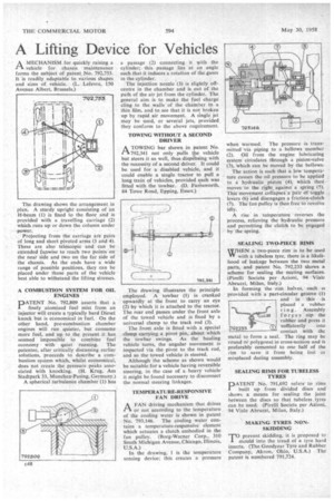
The drawing shows the arrangement in plan. A sturdy upright consisting of an 1-1-beam (1) is fixed to the floor and is provided with a travelling carriage (2) which runs up or down the column under power.
Projecting from the carriage are pairs of long and short pivoted arms (3 and 4). These are also telescopic and can be extended fanwise to reach two points on the near side and two on the far side of the chassis. As the ends have a wide range of possible positions, they can be placed under those parts of the vehicle best able to withstand the lifting stresses.
A COMBUSTION SYSTEM FOR OIL ENGINES "
pATENT No. 792,809 asserts that a finely atomized fuel mist from an injector will create a typically hard Diesel knock but is economical in fuel. On the other hand, pre-combustion chamber engines will run quieter, but consume more fuel, and up to the present it has seemed impossible to combine fuel
economy• with quiet running. The patentee, after critically discussing earlier solutions, proceeds to describe a combustion system which, whilst economical, does not create the pressure peaks associated with knocking. (H. Krug, Am Stadtpark 33, Munchen-Pasing, Germany.) A spherical turbulence chamber (1) has a passage (2) connecting it with the cylinder; • this passage lies at an angle such that it induces a rotation of the gases in the cylinder. ,
The injection nozzle (3) is slightly offcentre in the chamber and is out of the path of the air jet from the cylinder. The general aim is to make the fuel charge cling to the walls of the cham6er in a thin film, and to see that it is not broken up by rapid air movement. A single jet may be used, or several jets, provided. they conform to the above requirement.
TOWING WITHOUT A SECOND DRIVER
ATOWING bar shown in patent No. 792,341 not only pulls the vehicle but steers it as well, thus dispensing with the necessity of a second driver. It could be used for a disabled vehicle, and it could enable a single tractor to pull a long train of vehicles, provided each was fitted with the towbar. (D. Farnsworth, 84 Tovie Road, Epping, Essex.)
The drawing illustrates the principle employed. A towbar (1) is cranked upwardly at the front to carry an eye (2) by which it is attached to the tractor. The rear end passes under the front axle of the towed vehicle and is fixed by a universal clamp to the track rod (3).
The front axle is fitted with a special .clamp carrying a pivot pin, about which the towbar swings. As the hauling vehicle turns, the angular movement is imparted via the pivot to the track rod, and so the towed vehicle is steered.
Although the scheme as shown would be suitable for a vehicle having reversible steering, in the case of a heavy vehicle it might be found necessary to disconnect the normal steering linkages.
TEMPERATURE-RESPONSIVE FAN DRIVE
A FAN driving mechanism that drives or not according to the temperature of the cooling water is shown in patent No. 793,146. The cooling water contains a temperature-responsive element which actuates a clutch embodied in the fan pulley. (Borg-Warner Corp., 310 South Michigan Avenue, Chicago, Illinois, U.S.A.)
In the drawing, 1 is the temperature sensing device; this creates a pressure when warmed. The pressure is transmitted via piping to a bellows member (2). Oil from the engine lubricating system circulates through a piston-valve (3), Which can be moved by the bellows.
The action is such that a low temperature causes the oil pressure to be applied to a hydraulic -piston (4), which then moves to the right against a spring (5). This-movement collapses a pair Of-toggle levers (6) and disengages a friction-clutch (j). The faripuIley is-then free toieVolVe idly.
A rise in temperature reverses the process, relieving the hydraulic pressure and permitting the clutch to he engaged by the spring.
SEALING. TWO-PIECE RIMS WHEN a ' two-piece rim is to be used VI' with a tubeless tyre, there is a likelihood of leakage between the two metal parts, and patent No. 792,233 shows a scheme for sealing the mating surfaces. (Pirelli Societa per Azioni, 94 Viale Abruzzi, Milan, Italy.)
In forming the rim halves, each is provided with a part-circular groove (1) and in this is placed a -rubber ring. Assembly forces nip the rubber and press it
sufficiently into contact with the metal to form a seal. The ring may be round or polygonal in cross-section and is preferably cemented to one half of the rim to save it from being lot or misplaced during assembly.
SEALING RIMS FOR TUBELESS TYRES
PATENT No. 791,692 refers' to rims built up from divided discs and shows a means for sealing the joint between the discs so that tubeless tyres can be used. (Pirelli Societa per Azioni, 94 Viale Abruzzi, Milan, Italy.) MAKING TYRES NONSKIDDING To prevent skidding, it is proposed to L mould into the tread of a tyre hard inserts. (The Goodyear Tyre and Rubber Company, Akron, Ohio, U.S.A.) The patent is numbered 791,724.