


BUS AND MOTOR COACH SPRINGING.
Page 44
If you've noticed an error in this article please click here to report it so we can fix it.
A Résumé of Recently. Published Patents.
There are few who deny that the one part of a commercial motor vehicle (and particularly that designed for passenger work) Which is most, in need of reform is the suspension. Inventions to that end are not lacking, but, so far, nothing of practical commercial value seems to have been evolved. We have frequently, in times past, and again recently, drawn attention to the matter, both editorially, and by the publication of descriptive and technical articles concerning this department of design.
It is probably a fact that no concern in the whole world is better able to judge of the importance of this matter, at least in regard to passenger vehicles, than the London General Omnibus Co., Ltd. Not only is this company's actual experience of use wider and more varied than that of any other concern, but, as is wellknown, every invention, every idea for the improvement of heavy vehicle chassis is brought before their notice at one timc or another, by some means, either direct or indirect. Their knowledge and experience is naturally available to that allied concern, the Associated Equipment Co., Ltd., hence the importance which attaches to any invention emanating from either concern, and hence the interest which is inseparable from patent No. 178,288, by R. Kerr Thomas and the A.E.C. This specification deals with springing, and embodies a means whereby varying loads can be dealt With efficie ently.
The mechanism of this springing is described with regard to " a single point of suspension," which means no more than the springing mechanism for one end of one axle. In previous inventions two springs have been so employed that while one of them is (always in oreration the other only commences to act when the load has increased to a certain extent. This effect has usually been attained by the employment of a lost motion connection between the second spring and the chassis. That is the principle underlying this invention, which, however, embodies the additional feature of a dashpot device for each such connection. Smoother. operation of the springing is thereby facilitated.
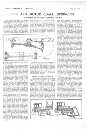
In the constructiou described in the body of the specification three springs are employed, all of the cantilever type, 1334 and all pivoted on the one shaft at their centres. Of the three only one, that in the middle, is in operation when the vehicle is unloaded. At its rear end this spring is attached to a bracket on the axle; at its front end it is supported in a bracket mounted upon the vehicle frame, the latter attachment being such as to allow longitudinal movement of the spring as it works. A ball-jointed radius rod is provided.
The other two springs are arranged to come successively into action as the load increases. To effect this the front ends of the springs are located at different levels relative to the chassis. They are coupled to the pistons of dashpots, and those pistons have a certain predetermined distance to travel before the spring becomes effective. This provides the needed lost motion.
Other Patents of Interest.
The principle of operation of the loading and unloading apparatus which is the subject of patent specification No. 178,177 is almost explained by one of oar illus trations. It will be observed that it consists of a small platform which is supported by a framework of parallel bars, which are hinged to the underside of the body of the vehicle. In one extreme position •the platform is on the ground level. It can be lifted from that to an intermediate one, in which, while still horizontal, it is, however, on the same level as the platform of the lorry. These are the two working positions. When not in use it is folded right up at the back of the lorry, when it takes the place of the tailboard. Several modifiea dons are described in the specification, which actually includes 48 different drawings. The patentees are V. L. J. Bourgeois and N. Dubois.
A tractor-trailer coupling,, designed to allow of positive steering of the latter by the driver of the former, is described in specification N. 178,376, by J. E. Serste. That portion of the coupling belonging to the trailer is attached to the pivot of its foreearriage. It carries an internally toothed segment, the teeth of which are set out on a pitch circle the centre of which is coincident with that of the fore: carriage. A shaft is carried on the tractor, and on it is mounted a sleeve, to which is keyed a pinion which engages with the segment, the two being kept at the proper distance apart by distance rollers, which also serve to transmit the drawbar effort of the tractor from this shaft to the rim of the, segment. The driver controls movement of the pinion by a steering wheel aud suitable connect, ing shafts and gears.
No. 178,137, by A. A. Remington, deals with a vaporizer. So far as the drawings which accompany the specification are concerned, the device appears to be specially designed for use with the Ford engine ; its principle, however, is quite broad in respect.of its 'application. ft is placed between carburetter and induction manifold, and is heated by exhaust gases. The mixture and additi6rial air _pass through tubes in a easing which is filled with exhaust gases which pass these through on their way to the atmosphere. The chief feature of this invention appears to be that the additional air is separately heated and is introduced into the mixture after the latter hes left the carburetter. Moreover, the additional air supply is automatically controlled in conjunction with the throttle.
A rather ingenious method of constructing a poppet valire with a tubular stem and separate head is described in No. 178,192, by W. Barrs.
W. S. Smith, in No. 156,206, describes it method of making the drag-link for steering gear. The link is made from a piece of tubing, enlarged at the ends to form sockets for the hall pins, which are held between springs and nads. All the parts are stamped or pressed. Nos. 156497 and 157;148, both by the same patentee (F.._ Schaefer), show methods of making brake connections from stamped parts and tubing. Lightness and economy are the objects which, it is claimed, are achieved by the constructions described.