


MAKING BEST USE OF THE FORD.
Page 26
If you've noticed an error in this article please click here to report it so we can fix it.
Valuable Advice on Every Phase of Ford Transport, which will Appeal to the Owner, Driver, and Repairer.
402.—Facilitating Chassis Reassembly.
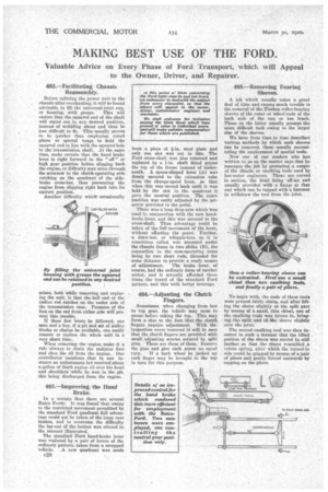
Before refitting the power unit to the , chassis after overhauling, it will be found advisable to fill the universal-joint cup, or housing, with grease. This will ensure that the squared end of the shaft will stand out in any desired position, instead of wobbling about and thus be less difficult to fit. This usually proves to be quicker than employing coned pliers or special tongs to hold the squared end in line with the squared hole in the transmission shaft. At the same time, make certain that the hand brake lever is right forward in the " off" or high gear position before slinging back the engine, or difficulty may arise through the setscrew in the clutch-operating arm catching on the quadrant of the sidebrake cross-bar, thus preventing the engine from slipping right back into its correct position.
Another difficulty which occasionally arises, both while removing anti replacing the unit, is that the ball end of the radius rod catches on the under side of the transmission case. Pressure of the foot on the rod from either side will prevent this trouble.
If these few hints be followed, one man and a boy, if a pit and set of Pulley blocks or chains be available, can easily remove or replace the whole unit in a very short time.
When removing the engine make it a rule always to drain the radiator first and then the oil from the engine. Our contributor mentions that in one instance an unfortunate laS received about a gallon of black engine oil over his head and shoulders while he was in the pit, this being discharged from the engine.
403.—Improving the Hand Brake.
In a Pertain fleet there are several Baico Fords. It was found that owing to the restricted movement permitted by the standard Ford quadrant full advantage could not be taken of the large rear brakes, and to overcome the difficulty the lay-out of the brakes was altered in the manner illustrated.
The standard Ford hand-brake lever was replaced by a pair of levers of the ordinary pattern, taken from a scrapped vehicle. A new quadrant was made from a piece of g-in, steel plate and only one slot was cut in this. The Ford cross-shaft was also removed and replaced by a 1-in, shaft fitted across the top of the frame instead of underneath. A spoon-shaped lever (A) was firmly secured to the extension tube from the change-speed lever, so that when this was moved back until it was held by the slot in the quadrant it gave the neutral position. The exact position was easily adjusted by the setscrew provided in the pedal.
There was a long drop-arm which '4 vas used in conjunction with the new handbrake lever, and this was secured to the cross-shaft. Thus advantage could be taken of the full movement of the lever, without affecting the sears. Further, a draw-bar, or whippre-tree, as it is sometimes called, was mounted under the chassis frame in two slides (B), the connection to the cam-operating arms being by two short rods, threaded for some distance to provide a ready means
of adjustment, Tire brake lever, of course, had the ordinary form of ratchet sector, and it actually afforded three times the travel of the standard Ford pattern, and this with better leverage.
404.—Adjusting the Clutch Fingers.
Sometimes when changing from low to top gear, the vehicle may seem to pause befora taking the top. This may form a clue to the fact that the clutch fingers require adjustment. With the inspection cover removed it will be seen that the clutch fingers are provided with small adjusting screws secured by split pins. There are three of these. Remove the pins and give each screw an equal turn. If a back wheel be jacked up each finger may be brought to the top in turn for this purpose.
405.—Removing Fearing Sleeves.
A job which usually takes a great deal of time and causes much trouble is the removal of the Timken roller-bearing sleeves of the outer or wheel ends of the back axle of the van or ton truck. Those on the latter usually present the more difficult task owing to the larger size of the sleeves.
We have from time to time described various methods by which such sleeves can be removed, these usually necessitating the employment of special tools.
Now one of our readers who has written to us on the matter says that he manages the job by procuring a couple of the chisels or caulking tools used by hot-water engineers. These are curved in section, the head being off-set and usually provided with a flange at that end which can be tapped with a hammer to withdraw the tool from the joint.
To begin with, the ends of these tools ware ground fairly sharp, and after lifting the sleeve slightly at the split part by means of a small, thin chisel, one of the caulking tools was driven in, bringing the split end of the sleeve slightly over the joint.
The second caulking tool was thea inserted in such a manner that the lifted portion of the sleeve was moved in still farther so that the sleeve resembled a volute spring, after which the turned-in side could be gripped by means of a pair of pliers and gently forced outwards by tapping on the pliers.