


A NEW HYDRAULIC CLUTCH.
Page 26
If you've noticed an error in this article please click here to report it so we can fix it.
A Résumé of Recently Published Patents.
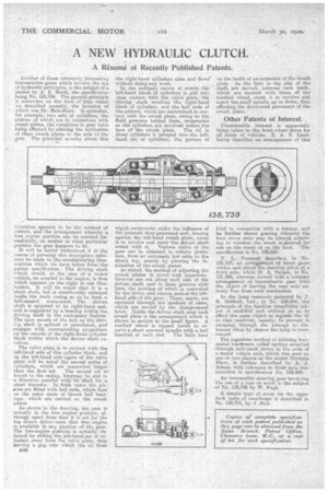
Another of those extremely interesting transmission gears which involve the use of hydraulic principles, is the subject of a patent by A. E. Eudd, the specification being No. 138,739. The general princip!e is somewhat on the lines of that which we described recently, the inventor of which was Dr. Hele-Shaw. It embodies, for example, two sets of cylinaers, the pistons of whieh, are in connection with swaeh plates, the variations in gear ratio being effected by altering the inclination of these ewaeh plates to the axis of the gear. The Principal novelty about this invention appears to be the method of control, and the arrangement whereby a free engine position can be reached immediately, no mattes in what particular position the gear bappens to be.
It will be. better understood if in. the course of perusing this descriptioe reference be made to the accompanying illustrations which wn have taken from the patent specification. The driving shaft which would-, in the case of a motor vehicle, be.coupled to the engine, is that which appears on the right in our illustration. It will he noted that it is a 'short shaft, but is considerably enlarged inside the main casing so as to form a bell-shaped component. The driven shaft is spigoted at its right-hand end, and is supported by a bearing within the driving shaft in the customary fashion., The open mouth of the hell on the driving shaft is splined or castellated, and „engages with corresponding projections op the outside of the right-hand cylinder block within which the driven• shaft revolves.
The valve plate ie in contact with the left-hand side of this cylinder block, and on the left-hand side-again of the valve plate will be noted the second series Of cylinders, which ate emnewhat larger
than the first set. The second set let keyed to the easing, buttmay be slid in a `direction parallel withits shaft for a short distance. In 'both cases the pisetons are fitted with ball ends, which bear 4111 the outer races of thrust ball bearings. which are carried on the awash plates
As shown in the drawing, the gear is actually in the free engine position, although apart from that it is set for the top direct drive—note that free engine is available in any position .of the gear. The free-engine. position is actually -obtained by sliding the left-band .set of cylinders away from the valve plate, thus leaving a gap into which the ell from
B3fi the right-hand cylinders ebbs and flows' 'without doing any work. In the ordinary course of events the left-hand block Of cylinders is slid into close contact with the valve plate, the 'driving shaft revolves the rightehand block of cylinder; and the 'ball ends of the pistons which are maintained in. contact with 'elle awash plate, owing to the fluid pressure behind them, reciprocate as the cylinders are revolved before the face or the awash plate. The oil in those cylinders is pumped into the lefthand set of cylinders, the pistons of
which reciprocate under the influence of the pressure thus generated and, bearing against the left-hand awash plate, cause it to revolve and carry the driven shaft round withit. 'Various ratios of the gear can be obtained in infinite gradetionefrom an extremely low ratio to the direct top, merely .by altering the inelination of the swash plates. As stated, the method of adjusting the awash plates is novel arid ingenious. Grooves are cut along each side of the driven shaft, and in theee grooves slide bars, the position of which is controlled by the levers and sleeves seen at the lefthand side of the gear. These, again, are operated through the -medium of cams, evlilch are moved by the change-speed lever. Inside the driven shaft near each awash plate is the arrangement which is shown in section in the small figure. A toothed wheel is tapped inside to receive a. short screwed spindle with a ball inserted at each end. The balls bear 'on the inside of an extension of the •gwasili. plate. As the bars in-the side of the shaft are moved, internal rack teeth, which are meshed with those of the toothed wheel, ea-use it to revolve and screw the small spindle up or down, thus effecting the downward movement of the awash plate.
Other Patents of Interest.
Considerable interest is apparently being taken in the front-wheel drive for all kinds of vehicles. .T. A. N. Leadbettv describes anarrangement of this
kind in connection with a, tractor, and he further shows gearing whereby the final drive ratio may be altered according to whether the truck is eiesired for use on the roads or on the land. The specification is No. 138,686. .
. F. L. Freernart describes, in No. 138,787; an arratueetnent of bevel gears within and about the steering pivot of. a frent axle, while M. A. Delve, in No. 121,289, concerns herself with a compact arrangement of transmission gear with the object of leaving the rear axle' entirely free from such mechanism.
In the lamp reservoir patented by J. R. OldfieM, Ltd., in No. 138,844, the principle of the familiar unspillable inkpot is modified and utilized so as to effect the sa-me object as regards the nil in that reseivoir, namely, to prevent it escaping through the passage to the burner when by chance the lamp is overturned.
. The ingenious method of utilizing hoeizontal transverse coiled springs attached through bell-crank levers to the ends of a motor vehicle axle, which was seen on one or two chassis at the recent Olympia Show, is further described hv A. J. Adams with reference to 'front axle construction in specification No. 138,804. An irreversible steering gear involving the use of a 4;41111 or scroll is the subject of No. 138,748 by W. Pugh.
A simple type of cover for the upper deck seats of omnibuses is described in No. 138,731, by J .Bull.