


Patents Completed.
Page 22
If you've noticed an error in this article please click here to report it so we can fix it.
A Motor Attachment for Lawn Mowers. For Turning in Restricted Areas. Laminated Spring Improvements. An Interesting Spray Carburetter.
Copies of complete specifications of the patents published on this page can be obtained from the Sales Branch, Patent Office, Holborn, W.C. at the cost of sixpence for each specification.
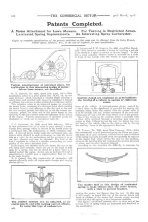
W. E. RENDLE, No. 6284, dated 27th April, 1915.—This specification refers to a prior patent (No. 10,371, 14), by the same inventor, which described a wheeled frame carrying a petrol motor and provided with means for attaching it behind an ordinary lawn mower or other similar slowly-taiiving vehicle.
This invention refers to an improved means for attaching the motor frame, consisting of a universal joint which permits the motor frame to rock sideways or the rear end to rise and fall over unequal ground, but does not, as did the former construction, permit the front end of the motor frame to rise relatively to the lawn mower under the influence of the torque of the engine. -Various constructions of universal joints are illustrated of which one is reprodueed herewith.
J. C. CotmomnE, No. 2699, dated 19th February, 1915.— In this carburetter the air is made to pass through a downwardly bent passage which is crossed at its lowest point by a perforated tube, the perforations of which constitute fuel. jets. A grooved sleeve works inside the perforated tube, one groove being allotted to each perforation, so that the sleeve acts as a valve for the perforations and by screwing it in or out their effective area may be adjusted. The level of the fuel is regulated by a float in a chamber surrounding the lower portion of the above described parts.
In the figure, two throttle valves are shown, the one on the left being used normally, while the one on the right is held open by a spring, but can be closed by a lever when it is desired to start the engine. In this case air is drawn through a supplementary conduit past a supplementary fuel jet close to the main throttle.
It is claimed that this construction of carburetter will operate efficiently under all engine-speed changes and varying suction effects.
J. !Armor; and F. W. MARTYN, No, 4469, dated 22nd March, 1915.—This invention provides a device for enabling a vehicle to be turned in a space as narrow as its own length. To this end a small auxiliary wheeled frame is mounted on a slide in front of the vehicle with the wheels at right angles to those of the vehicle. A rack-and-pinion device, worked by a hand wheel on -the. shishboard, is provided for Moving the auxiliary frame down into contact with the ground when it is to be brought into use, further movement of the rack-andpinion gear serving to lift the front wheels clear of the ground. One of the wheels on the auxiliary frame is provided with a chain drive operated through a reversing gear from the engine so that, without leaving his seat, the. driver can turn the head of the vehicle either to the right or left by driving the auxiliary frame in the appropriate direction.
W. LANDAU, No, 2828, dated 22nd February, 1915.—With the conventional form of laminated spring the leaves are generally made of an equal thickness, with the result that the failure of the spring is usually brought about unexpectedly by rupture of the master leaf, which carries the eyes for the shackles, owing to the fact that this leaf undergoes the greatest reversals of stress, and therefore becorres fatigued.
According to this invention the difficulty is overcome by making the master leaf thinner than the rest. In this ease it will usually be fOund that onc of the shorter leaves will break in advance of the master leaf, thereby giving warning of the fact that the spring is in a dangerous condition.
The figures reproduced herewith serve to show WO of the several forms of spring which are illustrated and described in the specification.