


Abridgments of Interesting Patent Specifications.
Page 24
If you've noticed an error in this article please click here to report it so we can fix it.
No. 9,604, April 27th, x 9o4. "Engine Frame or Case and Gear Box and Mounting it upon the Car." The Wolseley Company, Limited, and H. Austin.—This invention has for its object to ensure perfect rigidity and alignment between the engine frame or case and the gear box, and secnre mounting of these upon the car framing without undue sacrifice of elasticity in such framing ; the said parts in
alignment being preferably utilised in carrying the steering spindle. Fig. i is a plain view of a chassis whereon is a fourcylinder engine and change-speed gear box, showing also the means by which the rear road wheels are driven from the gear box. The forward end of the casing (A B; is formed with a hearing (a) through which the forward end of the crank-shaft (1.■ passes, and this end of the shaft is adapted to receive a handle (e) by which the shaft may be revolved by hand to start the motor. The bearing (a) is formed with a bracket or lug which is bolted to a cross-hearer (e) of the car framing. The rear end of the casing (A B) is formed as a deepened and widened part, and within this portion of the casing is the usual combined fly-wheel and clutch. From the opposite sides of this .widened-out portion of the casing project brackets or lugs (f), which rest upon and are bolted to the sides (g) of the car framing. The change-speed gear box (H) is formed, at its end which is towards the motor, with an enlarged portion (K), which, at its face, is of the size of the .deepened and widened portion of the motor casing, and is bolted thereto, thus making the gear box a rigid structure with the motor casing. This entire structure is carried on three points of the framing only, namely, at the points (d, f, f) where the brackets of the casing are fixed to the framing, whereby cross strains are avoided or minimised. The bracket (h), which carries the lower end of the steering spindle (j) on which is mounted the worm, and which carries the worm wheel which is operated by such worm, is fixed to the casing (A B). The dashboard (L) is fixed to the casing (A B), and thus it, and consequently the parts which it carries, are all lifted out from the framing in lifting out the motor therefrom.
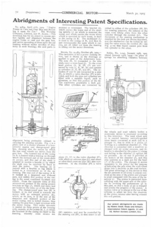
Brown, No. 21,283, October 4th, 1904.— This invention is for a power steering device, and is shown in the drawings as applied to gear of the Ackermann type. The rods (II, G) connected to the axle studs carry a cross head (j). To the cross head pistons (N, M, Gl, CI) are connected by rods (L, K, Bi, All and operate in cylinders (1', 0, Hi, and DI). The cylinders (P and 0) are connected by a pipe (R), in which a valve chamber (Fl) is provided, and both the pipe and cylinders are filled with a suitable liquid, such as glycerine, so that this portion of the device constitutes practically a dash pot. The other cylinders are connected by
pipes (JI, El) to the valve chamber (F1), with which an exhaust pipe (Li) and steam or other fluid pressure pipe (K1) also communicate. In the chamber (Fl) a valve mitted to either of the cylinders (Hi, DI) for steering purposes, the exhaust at the same time taking place from the other cylinder through the conduit (Li). The movement of the steering mechanism is steadied by the dash pot device described, and the mechanism can be locked by setting the valve across the conduit (R)—see Fig. 5—so that liquid cannot pass from one cylinder to the other.
Robin, No. r,o45, January igth, zgo5 (dated January 23rd, I9o4).—In place of springs for absorbing vibration between
the wheels and road vehicle bodies a pneumatic device is employed according to this invention. The road wheel axle (r) is carried between vertically-guided cross heads connected at each end to a plunger hi), free to slide in a piston (j) working in a cylindrical chamber (f). The chamber is connected with a reservoir (c) charged with air under pressure, and vibration is absorbed by the piston (j) rising and falling in the chamber (f) against the air pressure. An oil seal is provided at the bottom of the chamber (7), and this also operates as a dash pot for the head ( ji!of tha piston. The plunger (i) moves separately in the piston for the purpose of following the axle when the road wheel drops into a declivity in the road surface. The great advantage of this device is that the air pressure at all times is almost constant as the area of the piston and plunger is small compared with the area of the reservoir (c). The piston is prevented from colliding with the upper end of the cylinder by omitting the perforations (p) in this part, so that a body of air is trapped and arrests the progress of the piston_ A suction valve (q) is placed at the top of the cylinder to admit air from the reservoir as the piston returns after having entered this end portion.