Underfloor economy bus by Bristol
Page 56

Page 57

If you've noticed an error in this article please click here to report it so we can fix it.
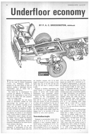
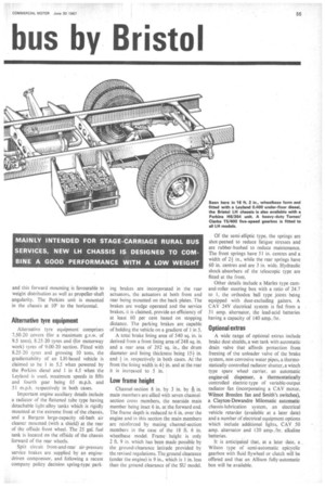
BY P. A. C. BROCKINGTON, AM1MechE THE new LH single-deck chassis announced this week by British Commercial Vehicles Ltd., Brislington, Bristol, is designed for the open market to cater for operators needing a lightweight low-cost "intermediate" type of vehicle with a relatively high performance.
The reason for its development? To overcome the difficulty of continuing to build the SU single-decker in view of the fact that the Albion EN 250 underfloor engine is no longer made.
Like its predecessor, the LH chassis should be particularly suitable for rural stage-carriage bus services and it is pertinent that underfloor mounting of the engine and the layout of the chassis generally facilitates the installation of different types of power unit (there is currently a choice of two units) varying the wheelbase and adapting the chassis to suit individual needs. A large number of options is offered, a lefthand-drive export chassis will later be available and it is notable that finalizing the design followed close consultation with a number of bodybuilders. Bodywork mounting is facilitated by the chassis layout, which includes a flat frame.
Although the LH has not the life expectancy or performance of the company's RE rear-engined chassis (and does not therefore compete with it) its kerb weight of around 3-1tons is some 14 tons lighter than that of the RE and the cost of the LH will show a saving of about £1,000.
Designed to facilitate maintenance, the chassis should, it is claimed, give, longer periods of service with normal routine maintenance than comparable vehicles produced by larger vehicle manufacturers.
About 50 SU single-deckers were produced last year; it is anticipated that there will be a yearly demand for many times this number of LHs, the production of which will be facilitated by the use of standardized proprietary units. Although, as mentioned, the chassis is mainly intended for stage-carriage work, underfloor mounting of the engine would enable a large rear luggage boot to be provided of the type required by some coach operators.
Three wheelbase lengths
Designed to accommodate bodies with a length of 22 ft. to 36 ft. the chassis is produced in three wheelbase lengths, the LH /S having a wheelbase of 12 ft. 6 in. and an overall length of 21 ft. 3 in., the LH a wheelbase of 16 ft. 2 in. and a length of 25 ft. 10 in. and the LI-1/L a wheelbase of
18 ft. 6 in. and a length of 28 ft. 2 in. The chassis are suitable for a maximum g.v.w. of 24,500 lb. (approximately 11 tons) and are offered with the Perkins H6 /354 diesel or the Leyland 0.400. In each case the torque is transmitted through a Turner / Clarke T5 /400 direct-mounted five-speed overdrive heavy-duty synchromesh gearbox to a BMC fully-floating 7-ton spiral-bevel back axle, the I-beam front axle being a standard Alford and Alder 44-ton unit having adjustable taper roller bearings. The overdrive top ratio of the gearbox is 0.79 to 1, the remaining ratios being fourth, 1.00 to 1, third 1.80 to 1, second, 3.27 to 1, first 5.95 to 1 and reverse 5.95 to 1. The rear axle affords a final drive ratio of 5.13 to 1.
In a typical example of a stage-carriage body mounted on a LH chassis, the body would have a weight of 24 tons, which would give an unladen weight of 6 tons.
For application to the LH chassis the Perkins engine is de-rated from 120 b.h.p. at 2,800 r.p.m. to 95 b.h.p. at 2,400 r.p.m. (maximum torque 244 lb. ft. at 1,000 r.p.m.) while the Leyland is used in standard form with a rating of 125 b.h.p. at 2,400 r.p.m. (maximum torque 300 lb. ft. at 1,600 r.p.m.). The front of the power unit is 34 ft. behind the front axle,
and this forward mounting is favourable to weight distribution as well as propeller-shaft angularity. The Perkins unit is mounted in the chassis at 10° to the horizontal.
Alternative tyre equipment
Alternative tyre equipment comprises 7.50-20 covers (for a maximum g.v.w. of 9.5 tons), 8.25-20 tyres and (for motorway work) tyres of 9.00-20 section. Fitted with 8.25-20 tyres and grossing 10 tons, the gradientability of an LH-based vehicle is claimed to be 1 in 5.5 when powered by the Perkins diesel and 1 in 4.5 when the Leyland is used, maximum speeds in fifth and fourth gear being 65 m.p.h. and 51 m.p.h. respectively in both cases.
Important engine auxiliary details include a radiator of the flattened tube type having detachable light-alloy tanks which is rigidly mounted at the extreme front of the chassis, and a Burgess large-capacity oil-bath air cleaner mounted (with a shield) at the rear of the offside front wheel. The 25 gal. fuel tank is located on the offside of the chassis forward of the rear wheels.
Split circuit front-and-rear air-pressure service brakes are supplied by an enginedriven compressor, and following a recent company policy decision spring-type park
ing brakes are incorporated in the rear actuators, the actuators at both front and rear being mounted on the back plates. The brakes are wedge operated and the service brakes, it is claimed, provide an efficiency of at least 60 per cent based on stopping distance. The parking brakes are capable of holding the vehicle on a gradient of 1 in 5.
A total brake lining area of 540 sq. in. is derived from a front lining area of 248 sq. in. and a rear area of 292 sq. in., the drum diameter and lining thickness being 154 in. and in. respectively in both cases. At the front the lining width is 4+ in. and at the rear it is increased to 5 in.
Low frame height
Channel-section 8 in. by 3 in. by h in. main members are allied with seven channelsection cross members, the nearside main member being inset 6 in. at the forward end. The frame depth is reduced to 6 in. over the engine and in this section the main members are reinforced by mating channel-section members in the case of the 18 ft. 6 in. wheelbase model. Frame height is only 2 ft. 9 in. which has been made possible by the ground-clearance latitude provided by the revised regulations. The ground clearance (under the engine) is 9 in., which is 1 in. less than the ground clearance of the SU model.
Of the semi-elliptic type, the springs are shot-peened to reduce fatigue stresses and are rubber-bushed to reduce maintenance. The front springs have 51 in. centres and a width of in., while the rear springs have 60 in. centres and are 3 in. wide. Hydraulic shock-absorbers of the telescopic type are fitted at the front.
Other details include a Manes type camand-roller steering box with a ratio of 24.7 to 1, the orthodox ball type joints being equipped with dust-excluding gaiters. A CAV 24V electrical system is fed from a 31 amp. alternator, the lead-acid batteries having a capacity of 140 amp. /hr.
Optional extras
A wide range of optional extras include brake dust shields, a wet tank with automatic drain valve that affords protection from freezing of the unloader valve of the brake system, non-corrosive water pipes, a thermostatically-controlled radiator shutter, a winch type spare wheel carrier, an automatic engine-oil dispenser, a thermostatically controlled electric-type of variable-output radiator fan (incorporating a CAV motor, Wilmot Breeden fan and Smith's switches), a Clayton-Dewandre Milomatic automatic chassis-lubrication system, an electrical vehicle retarder (available at a later date) and a number of electrical equipment options which include additional lights, CAV 50 amp. alternator and 120 amp. /hr. alkaline batteries.
It is anticipated that, at a later date, a Wilson type of semi-automatic epicyclic gearbox with fluid flywheel or clutch will be offered and that an Allison fully-automatic box will be available.


