


An Austin Anti-knock Cylinder Head
Page 86
If you've noticed an error in this article please click here to report it so we can fix it.
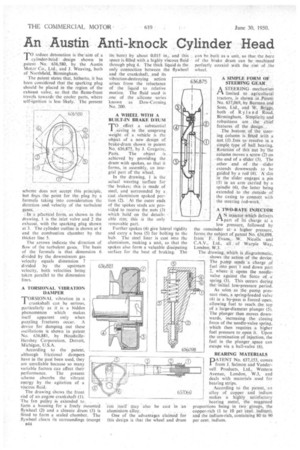
To reduce detonation is the aim of a 1 cylinder-head -design shown in _patent No. -636,580, by the Austin Motor Co., Ltd.. and I. Weaving, both of Northfield', Birmingham.
The patent states that, hitherto, it has been considered that the sparking plug should be placed in the region of the exhaust valve, so that the flame-front travels towards the cooler parts, where self-ignition is less -likely.' The present
scheme does not accept this principle, bat fixes the point for the. plug by a formula taking into consideration the direction and. velocity of the turbulent .a'a peactical form, as shown in the drawing, 1 is the inlet valve and 2 the exhaust, with the sparking plug shown at 3. The cylinder outline is shown at 4 and the combustion chamber by the thicker line 5.
The arrows indicate the direction of flow of the turbulent gases. The basis of the formula is that dimension 6 divided by the downstream gas velocity equals dimension 7 divided by the upstream velocity, both velocities being taken parallel to the dimension lines.
A TORSIONAL VIBRATION DAMPER.
TORSIONAL vibration in a 1 crankshaft can be serious, particularly as it is a hidden phenomenon which makes itself apparent only when puzzling fractures occur. A device for damping out these oscillations is shown in patent No. 636,881, by Houclaille-* Hershey Corporation. Detroit, Michigan, U.S.A.
According to the patent, although frictional dampers have in the past been used, they are unreliable because so many variable factors can affect their performance. The present scheme absorbs the vibrant energy by the agitation of a viscous fluid.
. The drawing shows the front end of an .engine crankshaft -(l); The fan pupey, is extended to: ,
fOrm a housing for a freely mounted flywheel (2) and a closure drum (3) is fitted to form a sealed chamber. The flywheel clears its surroundings (except e44 its, bore) by about 0.015 in., and this space is filled with a highly viscous fluid through plug 4. The thick liquid is the only connection between the flywheel and the crankshaft, and its vibration-destroying action arises from the reluctance of the liquid to relative motion. The fluid used is one of the silicone series known as Dow-Corning No. 200. * • A WHEEL WITH A BUILT-IN BRAKE DRUM
TO effect a substantial _saving in the unsprung • weight of a. vehicle is the object of a new design of brake-drum shown in patent No; 636,875;byJ. Gregoire, Paris. The object is achieved by providing the drum-with spokes, so that it forms, in assembly, an integfal part or-the Wheel.
In the drawing, 1 is the actual Wearing surface for
brakes;this is made of steel, and surrounded by a cast. aluminium spoked portion (2). ' At the outer ends of the spokes studs are provided to receive the nuts (3) which hold oh the detachable rim; this is the only removable part.
Further spokes (4) give latera rigidity and carry a boss (5) for boWng to the hub. The steel liner is cast *nto the aluminium, making a unit, so that the spokes also form a valuable dissipating surface for the heat of braking. The
rim itself way also be cast in an aluminium alloy.
One of the advantages claimed for this design is that the wheel and drum can he built as a unit, so that the bore of the brake drum can be machined perfectly coaxial with the rim of the wheel.
A SIMPLE FORM OF STEERING GEAR
ASTEERING mechanism limited to agricultural tractors, is shown in Patent No. 637,069,. by Burman and Sons, Ltd., and W. Briggs, both of Ryland Road, Birmingham. Simplicity ahd robustness are the chief features Of the design: _ The bottom. of the steering column is fitted with a nut (I) free to revolve in a simple type of ball bearing. Rotation" of this nut by -the column moves a screw (2) on —the-end of a slider (3). The other end of the slider extends downwards to be guided by a rod (4). A' sIdt in the slider engages a pin (5) in an arm carried by a spindle (6), the latter being extended to the outside of the casing to connect with the steering iod-work.
A TWO-RATE INJECTOR
AN injector which delivers part of its charge at a low pressure, followed by the remainder ata higher pressure, forms the subject of patent No. 636,098, frorn. F. Evan,.W. Nicolls" and C.A.V., Ltd., all of Warple Way,
London, W.3.
The drawing, which is diagrammatic,
shows the action of the device. The pimp sends a charge of fuel into port 1 and down port 2, where it opens the needlevalve against the force of a spring (3). This occurs during the-initial low-pressure period.
As scion as the pump pressure rises, a spring-loaded valve (4) in a by-pass is forced open, allowing fuel to reach the top ..of a large-diameter plunger (5). The plunger then moves downwards, increasing the closing force of the needle-valve spring, which then requires a higher fuel pressure to open it. Upon the termination of injection, the fuel in the plunger space can escape via a ball-valve (6).
BEARING MATERIALS
PATENT No. 637,153, comes from J. Salmon and Vandervell Products, Ltd., Western Avenue, London, W.3, and deals with materials used for bearing strips.
According to the patent, an alloy of copper and indium makes a highly satisfactory bearing metal, the suggested proportions being in two gt-oups, the copper-rich (1 to 10 per *cent., indium), and the indium-rich, containing 80 to 90 per cent. indium.