A Two-way Clutch Design from America
Page 36

If you've noticed an error in this article please click here to report it so we can fix it.
I Tis rather surprising that the two
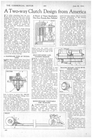
way clutch has not beee more widely adopted as by its use, the gear change most often required (from top to the next speed) can easily and quickly be performed. A design for a clutch of this nature comes, in patent. No. 561,014, from W. Thelander, Auburn, Indiana, U.S.A.
The clutch employs a single driving plate (1), which can be pressed into contact either with a disc (2) splined on the central shaft (3). or a disc (4) splined •to an encircling sleeve (5). Both the shaft and the sleeve enter the gearbox, where -each is connected to a different ratio, the central shaft giving the higher gear. The selector mechanism comprises a sliding sleeve (6) which, via toggle links, rocks one
of a pair of levers (7). These levers exert endwise pressure on a ring (8) to which the central clutch plate (1) is fixed. Ring 8 is made in halves, • separated by springs; this feature gives resilience to the action and allows for wear of the friction facings.
A DIAPHRAGM TYPE OF PETROL COCK
MOST fluid control cocks have some form of moving joint that has to iemain fluid-tight, and it is this part that eventually wears out and permits• leaks to develop. A cock, intended particularly for petrol, in which there are no moving joints that can possibly
leak, is shown in patent`No. 560,788, by C. Swain and Thomas Tilling, Ltd., both of Bovingdon, Herts.
In this design, the movable member consists of a flexible diaphragm (1) which is firmly clamped around its edge, leaving its centre free to move. Fixed to the diaphragm is a boss (2) carrying-a sealing washer which opens or closes the petrol exit (3). The boss is biased towards the closed position by a spring, but it can be opened by a hel'cal cam (4), which over:ornes the spring when manually 'moved through an angle of 90 degrees.
SELF-CONTAINED LOW.
LOADING TRAILER •
FROliel J. Dyson, T. Pollard and F. Barker, all of 76-80, Grafton Street, Liverpool, comes, in patent No. 560,512, a design for atrailer, the frame of which can be lowered to the ground. The main advantage is that no jacks or other 'loose members are required, all the hoisting mechanism being pai•t of the trailer itself.
• The drawing shows the frame in the " down " position, resting entirely on the ground. The lowering mechanism at the front end consists, primarily, of a jack-screw (1) on the axle assembly, engaging a nut member (2) on the
frame of the trailer. doublehandled crank, with reduction gear, enables the operator to raise or lower the frame about the pivot.(3).
The rear end is also worked by a similar hand gear, the lifting member, in this case, consisting of a drumwound cable (4). At this end the whole wheel and axle assembly leaves • the frame; pivoting about the pin (5).
The patent also covers the use. of the hoisting mechanism with a power drive.
OUICK-RELEASE TURNTABLE FOR TRAILERS
ATURNTABLE for a 'semi-trailer and its coupling , arrangements form the subject of patent No. 560,743, from •C. Rydh, Virserum, Sweden. The objects are to give a
quick and easy release, also to provide adequate lubrication to the bearing discs of the turntable.
Referring to the drawing, the tractor frame. (1) carries the lower stationary disc (2) and the upper swivelling one (3). Gaps in the latter allow oil from a felt ring to percolate through on to the rubbing surfaces. On the upper disc is mounted a pair of free rollers (4) journalled on bolts carried by brackets (5 and 6). These rollers support the weight of the trailer frame (7) and transmit the pull via hooks (not shown), pivoted on this frame. The hooks embrace the rollers (4) and are locked by pawls, both members being operable by means of a quick-action lever. The brakes of the trailer are worked, by an axial push-rod (8) acting in the well-known manner.
SEALING ROTARY VALVE WITH PISTON RINGS .
THE conventional piston ring is the only practicable method of holding hot gases under pressure, and a scheme for sealing a rotary valve by this means forms the subject of patent No. 560,581, from F. Wilkinson, 37, Lower Hillmorton Road, Rugby.
The rotary valve described is formed in the shape of a sphere, a n d, as shown in the drawing, would he rotated about a
561:4581 vertical axis. An
axial port on the underside leads to a port (1) in the side 'which traverses the inlet and exhaust ports in the well-understood manner. The sphere is provided With a pair of cross-over grooves (2) in which are placed two piston rings, the gap of each being wide enough to allow the other to pass through. Another cross-over pair (3) is arranged around the port, and a similar pair is placed diametrically opposite. The only non-standard feature of the rings is their outside form; this would, of course, have to conform with the spherical outlirre.
The use of such a spherical valve lends itself to the use of normal rings, and there is the advantage that the rings are continually wiping the area of the valve chamber and helping lubrication.


