


Patents Completed.
Page 22
If you've noticed an error in this article please click here to report it so we can fix it.
Complete specifications of the following patents will be sent to any address in the United Kingdom upon receipt of eightpence per copy at the Sale Branch, Patent Office, Holborn, W.C.
VALVE C;EAR.—Roots.--.No. 8,824, dated 14th April, 1909.—This invention relates to valve gear of the sliding-piston type for internal-combustion engines. The valve comprises a cylindrical casing, which is open at one end to the exhaust pipe, and which has a port communicating with the combustion chamber of the cylinder and another port communicating with the inflection pipe. Within the casing is a hollow piston, in which are arranged exhaust and inlet ports, the exhaust ports being separate from the inlet ports by a curved dividing wall. A spiral spring is interposed between the valve casing and a shoulder on the piston, and this spring tends to force the piston valve against an operating cam, the piston being provided with an anti-friction roller. In one illustration, part of a four-cylinder engine is shown in which the valves are arranged at 00 degrees relatively to each other; in the other, an alternative method of operating a valve is shown.
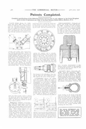
RESILIENT WTI REL.—Chertemps. — No. 1,526;1910, dated under Convention 30th January, 1969.—This wheel comprises two circular plates bolted together with distance pieces interposed between them. These plates support the rim which carries an india-rubber tire. The wooden spokes of the wheel extend between the circular plates and support a wooden feline, in which is arranged a number of transversely-disposed cylinders. These cylinders are closed at one end and each contains a spiral spring, which latter bears against the closed end of the cylinder at one end and a ring at the other end, which latter forms a seating for a ball. The ball is pressed by the spring into contact with a conicallyshaped recess formed in the circular side plates of the wheel. The operation is as follows. When under load, the rim carried by the plates becomes displaced relatively to the wooden feline carried by the spokes, and consequently the balls are caused to ride on the conical faces of the recesses in the side plates, thus forcing the balls into their respective cylinders against the action of the springs.
TA XTMETERS.-13ruhn.—No. 18,019, dated 4th August, 1909.—The object of this invention is to provide an improved arrangement for preventing fraudulent manipulation of the taximeter. The invention has special reference to that type of taximeter wherein the indicating discs are arranged to he covered or uncovered by a slide that Is operated in conjunction with the flag. The shutter is operated by a rotating cam through the medium of a pivoted lever, which latter is connected to the slide or shutter by means of a pin. With this arrangement the slide or
shutter is not moved until the flag or set. ting lever has almost completed its movement, thus ensuring the registering mechanism's being brought. into gear before the indicating discs are exposed to view.
TIRE FASTENING S.—G oldsmith and Others.—No. 27,367, dated 24th November, 1009. According to this invention a tire is secured to the rim of a wheel by a number of bolts extending through the felloe of the wheel. The heads of the bolts are sunk into the body of the tire and the hole is then plugged and vulcanised. In order to prevent the tire
from becoming disintegrated, a cupshaped washer of leather or like material is interposed between the head of the bolt and the india-rubber.
SECURITY BOLT.—Grimwade.—No. 20,369. dated 6th September, 1909.— This security bolt is formed with a plain portion of reduced diameter. It often happens that the portion of the bolt projecting beyond the feline of the wheel becomes bent, and, consequently, it is very difficult to remove the wing-nut. With the present arrangement, however, the slight bending of the shank of the bolt does not, in the least, interfere with the removal of the wing-nut, as the latter, on being disengaged from the first portion of the thread, slides along the blank or plain portion of the bolt. A further advantageous feature of this bolt is that it can be very quickly loosened when changing the inner tube.