


A Loading Gear for Lorries
Page 58
If you've noticed an error in this article please click here to report it so we can fix it.
REAR MOUNTED self loading mechanisms are becoming very popular and a device of this nature is shown in patent No. 711,235 (E. Jensen, Roald Amundsensgt 1, Oslo, Norway). The chief novelty -in this design is a means for preventing the load from rolling off the platform during lifting.
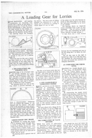
• The drawing shows the swinging frame (1) which is pivotally connected to the back of the vehicle. The frame is raised or lowered by a hauling cable (2). The cable goes round a pulley and is secured to one arm of a rocking cradle (3).
When the load (in this case a drum) has been rolled on to the cradle, the first movement of the cable rocks the cradle into the upper position (4), so that the drum is prevented from rolling off.
A DELAYED-ACTION OILSCRAPING RING DISTON rings of the oil-scraper type are scarcely necessary on a new engine. A delayed-action ring which does not start to function until wear has occurred, is shown in patent No. 710,950, which comes from the British Piston Ring Co., Ltd., and T. Twigger, both of Holbrook Lane, Coventry. The drawing shows one view of the ring, which is grooved externally to
form a channel-section. Numerous slots (1) connect the bottom of the channel with the interior. The chief point is the provision of small projecting lands (2) which at first make contact with the cylinder walls and hold the ring substantially out of action. The lands are only about 0.002 in. high, and when they have worn away the ring can make full contact and then start to function fully.
LIQUID-COOLED DISC BRAKE A SCHEME for cooling disc brakes rt by pumping liquid through them, is shown in patent No. 711,059. This comes from Dunlop Rubber Co., Ltd., 1 Albany Street, London, N.W.1. It is stated that by using these cooled brakes, much smaller units can be used and so weight can be saved.
The drawing shows a general view of A40 The disc, at its lowest point, dips into the liquid and so disposes of much of its heat. The brake may be cooled by engine oil flowing in the pipe circuit (3) or a special liquid may be employed; in the latter case a separate transmission-driven pump would be used.
A NEW DAIMLER-BENZ COMBUSTION SYSTEM rt/TANY and diverse are the improve' V1 ments in combustion systems suggested by Daimler-Benz A.G., Stuttgart-Unterttirkheim, Germany, and still another is shown in patent No. 711,023. The objects of this one are to reduce " hammering " during idle running and to lower fuel consumption.
In the drawing, a pre-combustion chamber (1) leads, via a restricted neck, to a recess (2) in the piston crown. The neck in this instance consists of an annular space formed round a central rod (3).
The rod is fitted with a flange (4) the object of which is to act as a baffle and spread the fuel evenly into the air charge in the piston recess. The rod has to be accurately centred on the chamber axis and this is achieved by mounting it upon two cross-pins (5 and 6) lying at right-angles to each other.
THE LUBRICATION OF VALVE ROCKERS
THE finer points of valve-rocker lubrication for heavy-duty engines are discussed in patent No. 709,820, which comes from Toledo Stamping and Manufacturing Co., Toledo, Ohio, U.S.A. It is suggested that it is preferable to limit the oil supply to the end
of the rocker over the valve because an excess at this point tends to run down the valve-stem eventually to be burnt in the cylinder.
The drawing shows an improved rocker assembled from a pair of steel stampings. The oil arrives through port 1 and, after lubricating the shaft, passes upwards through passage 2.
It then flows into a well, formed between the two stampings and runs to the left along slot 3 to bathe the ballend (4).
The oil that runs to the right is limited by a dam (5) so that the quantity reaching the valve-contacting end (6) does not exceed that necessary for adequate lubrication.
AN INDICATOR FOR LIQUID LEVEL
PATENT No. 710,980 (Bendix Aviation Corp., 30 Rockefeller Plaza, New York, U.S.A.) shows an electrically operated liquid-level indicator. Its particular purpose is to convey to the driver the fact that the _level of the fluid in the hydraulic brake reservoir is satisfactory; it could, of course, be applied to many other purposes. The operative unit is a " thermistor " (1) which is a sintered mixture of ceramic and metallic oxides. It has the property of giving a negative co-efficient of resistance; in other words, the hotter it gets, the more current will it pass.
By constructing the simple circuit shown in the drawing, a lamp (2) can be made to light if the liquid in the reservoir falls below the thermistor. The action is that., normally, the liquid keeps the thermistor cool, and its resistance is then high enough to pass but very little current.
But should the level fall below the unit, the still air would have very little cooling effect and the device would rapidly heat up. The action is cumulative owing to the negative resistance, and in a second or so the lamp will light.