


Novel Method of Starting Oil . Engines A Résuméof Patent Specifications
Page 56
If you've noticed an error in this article please click here to report it so we can fix it.
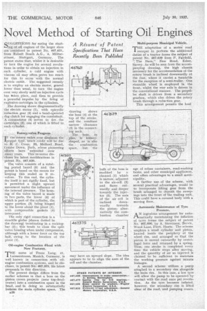
That Have Recently Been' Published "GGF.STIONS for easing the start ing Of oil engines of the larger sizes are contained in patent No. 467,621, from Robert Bosch A.G., 4, Militarstrasse, Stuttgart, Germany. The patent states that, whilst it is desirable to turn the engine for several revolutions in order to obtain an injection in each cylinder, a cold engine with viscous thl may often prove too much for this to occur with the normal electric outfit. The suggested remedy is to employ an electric motor, geared lower than usual, to turn the engine over very slowly until an injection cycle has inken place, and then to provide a powerful impulse by the firing of explosive cartridges in the cylinders. The drawing shows diagrammatically the electric motor (1),. with epicyclic 'reduction gear (2) and a hand-operated dog clutch for engaging the crankshaft. A commutator (4) serves to fire the Cartridges (3), one of which is filted to each cylinder.
Rotary-valve Progress. Rotary-valve Progress.
" IF the rotary valve .ever displaces the 'poppet type, much credit will be due In R. C. Cross, 33, Midford Road, Ccari.t>e' Down, path, whose pioneering eflorts have extended over many years. This' inventor discloses his latest modifications in patent No. 467,620. The valve consists of a rotating ported barrel (5) and,' the patent is based on the means for keeping this sealed as it revolves. To this end, the cylinder itself is not rigidly fixed, but is permitted a slight upward movement under the influence of the internal pressure. The housing of the valve barrel is made in two parts, the lower (6) of which is part of the cylinder, the upper portion (3) being hinged to the lower about the pivot (1), with compressible gaskets (4) interposed.
The only rigid connection is a straddle girder (shown dotted in the drawing) terminating in a rockingbar (2); this tends to close the split valve housing when under compression, although with a lesser force on the top half, owing to the location of the pivot (1).
Oil-engine Combustion 4-lead with New Features.
THE name of Franz Lang, 41, 1 Lairnerstrasse, Munich, Germany, is well known in connection with oilengine combustion systems, and be discloses, in patent No-. 467,375, his latest proposals in this direction. The present design differs from the earlier schemes in that a boss on the piston crown projects (near top-deadcentre) intoa combustion space in the head, and -in doing so substantially isolates the main cylinder space. The
A38 Multi-purpose Municipal Vehicle.
THETHE adaptation of a motor road to perform the additional duties of a tractor forms the subject of patent No. 467,639 from P. Fairfield, The 13arn,'' New Road, Esher, Surrey. As will be seen from the accompanying drawing, the high chassis necessary for the accommodation of the rotary brush is inclined downwardly at the rear, where it carries a turntable for the reception of a semi-trailer. One steerable wheel is employed in the front, whilst the rear axle is driven in the conventional manner. The propeller shaft is driven from a secondary gearbox, which also drives the rotary brush through a reduction gear. This arrangement permits the haul age of refuse containers, road-washing tanks, and other municipal appliances. and offers advantages to a small municipality. A further usek of the scheme, with several practical advantages, would be to incorporate lifting gear from the brush arranged to deposit the sweepings into the front of the trailing unit. This could have a covered body with a moving floor.
Automatic Maintenance of Tyre. Pressure. AN ingenious arrangement for automatically maintaining the inflation of tyres forms the subject of patent No. 467,096, by A. Stevenson-, Bervie,
Wood Lane, Fleet, Hants. The scheme employs a small cylinder and piston, located inside the periphery of the wheel rim, and arranged so that the piston is moved outwardly by centri-. fugal force and returned by a spring.
s, e
Thu on stroke is completed every time the vehicle stops after moving, a and the quantity of air so injected is claimed to be sufficient to maintain the working pressure against minute leakages.
A second scheme utilizes a pump
atta secondary fhed to a seconda -rim alongside the main rim. In this case, a low tyre
will allow the pump to be operated bycontact with the road once per revolu
tion. As the tyre becomes inflated, however, the secondary rim is lifted clear of the road, and pumping ceases.