


A Novel Form of VALVE MECHANISM
Page 70
If you've noticed an error in this article please click here to report it so we can fix it.
A Wsurne of Recently Published Patent Specifications.
TIlE valve-actuating mechanism described in specification 1 No. 314,217 by F. W. Giles, of Trimpley, Woodfield Avenue, Penn, Wolverhampton, contains what appears to be a novel feature. The specification points out that in highspeed internal-combustion engines tho valves have to be operated by very strong springs to ensure their proper operation by preventing lag and bounce.
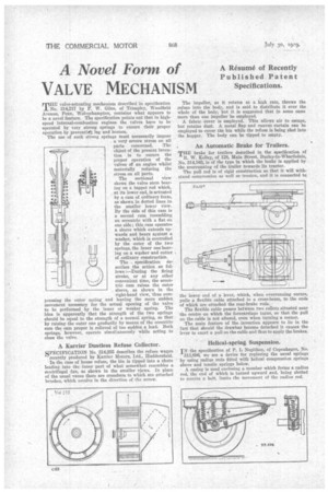
The use of such strong springs must necessarily impose , a very severe stress on all parts concerned. The object of the present invention is to ensure the proper operation of the valves of an engine whilst materially reducing the stress on all parts.
The sectional view shows the valve stem bearing on a tappet rod which, at its lower end, is actuated by a cam of ordinary form, as shown in dotted lines.in the smaller lower view. By the side of this cam is a second cam resembling an eccentric with a fiat on one side; this cam operates a sleeve which extends upwards and bears against a washer, which is controlled by the outer of the two springs, the inner one bearing on a washer and cotter of ordinary construction.
The specification describes the action . as follows :—During the firing stroke, or at any other convenient time, the eccentric cam raises the outer sleeve, as shown in the right-hand view, thus compressing the outer spring and leaving the more sudden movement necessary for the actual opening of the valve to be performed by the inner or weaker spring. The idea is apparently that the strength of the two springs should be equal to the strength of a normal spring, so that by raising the outer one gradually by means of the eccentric cam the cam proper is relieved of too sudden a load. Both springs, however, operate simultaneously while acting to close the valve.
A Karrier Dustless Refuse Collector.
SPECIFICATION No. 314,255 describes the refuse wagon recently produced by Karrier Motors, Ltd., Huddersfield.
In the case of house refuse, the bin is tipped into a chute leading into the inner part of what somewhat resembles a centrifugal fan, as shown in the smaller views. In place of the usual vanes there are crossbars to which are attached brushes, which revolve in the direction of the arrow. The impeller, as it rotates at a high rate, throws the refuse into the body, and is said to distribute it over the whole of the body, but it is suggested that in some easel more than one impeller be employed.
A fabric cover is employed. This allows air to escape, but retains dust. A metal flap and canvas curtain can be employed to cover the bin while the refuse is being shot into the hopper. The body can be tipped to empty.
• An Automatic Brake for Trailers.
THE brake for trailers described in the specification of It. W. Kelley, of 128, Main Street, Burley-in-Wharfedale, No. 314,103, is of the type in which the brake is applied by the overrunning of the trailer towards its tractor.
The pull rod is of rigid construction so that it will withstand compression as well as tension, and it is connected to.
the lower end of a lever, which, when overrunning occurs, pulls a flexible cable attached to a cross-beam, to the ends of which are attached the rear-brake rods.
The flexible cable passes between two rollers situated near the centre on which the forecarriage turns, so that the pull on the cable is not altered, even when turning a corner.
The main feature of the invention appears to lie in the fact that should the drawbar become detached it causes the lever to exert a pull on the cable and thus to apply the brakes.
Helical-spring Suspension.
IN the specification ,of P. L Negithon, of Copenhagen, No. 313,896, we see a device for replacing the usual springs by using radius rods fitted with helical compression springs above and tensile springs below.
A casing is used enclosing a member which forms a radius rod, the end of which is turned upward and, being slotted to receive a bolt, limits the movement of the radius rod.