


Patents Completed.
Page 20
If you've noticed an error in this article please click here to report it so we can fix it.
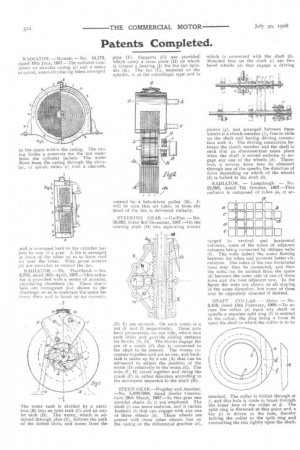
RADIATOR. — Howell. — No. 14,173, dated 19th June, 1907.—The radiator comprises an annular casing (a) and a series of spiral, water-circulating tubes arranged
in the space within the casing. The casing forms a reservoir for the hot water from the cylinder jackets. The water flows from the casing through the circular, or spiral, tubes (c) into a channel,
and is conveyed back to the cylinder jackets by way of a pipe. A. fan is arranged in front of the tubes so as to force cool air over the latter. Wire gauze screens (i'a) are provided to protect the fan.
RADIATOR. — De Havilland. — No. 9,708, dated 26th April, 1907.—This radiator is provided with a series of annular, circulating chambers (A). These chambers are corrugated (not shown in the drawings) so as to maintain the space between them and to break up air currents.
The water tank is divided by a partition (B) into an inlet tank (C) and an outlet tank (D). The water, which is admitted through pipe (E), follows the path • of the dotted lines, and issues from the pipe (F). Supports (G) are provided which carry a cross piece (H) on which is formed a bearing (J) for the fan spindle 1(). The fan (L), mounted on the spindle, is of the centrifugal type and is rotated by a belt-driven pulley (M), will be seen that air taken in from the front of the fan is delivered radially.
STEERING GEAR, —Guillon.— No. 26,662, dated 3rd December, 1907.—On the steering shaft (M) two separating worms
(D, E) are secured. On each worm is a nut (I! and II respectively). These nuts have projections, on one side, which face each other and provide sliding surfaces for blocks (N, 0). The blocks engage the pin of a crank (R.) that is connected to the shaft to be steered. The worms cooperate together and act as one and backlash is taken up by a nut (A) ;hat can be Advanced to adjust the position of the worm (D) relatively to the worm (E). The nuts (14', H) travel together and swing the crank (P) in either direction according to the movement imparted to the shaft (M).
SPEED GEAR.—Dugelay and Another. —No. 5,876/1908, dated (under Convention) 29th March, 1907.—Iit this gear two
parallel shafts c) are employed. The shaft (c) can move endwise, and it carries feathers (1) that can engage with any one of three wheels (k). These wheels are geared with three other wheels fast on the casing of the differential gearbox (d), which is connected with the shaft (b). Mounted free on the shaft (c) are two bevel wheels (h) that engage a driving pinion (g), and arranged between these wheels is a clutch member (j), free to slide on the shaft and having driving connection with it. The driving connection between the clutch member and the shaft is such that no disconnection takes place when the shaft is moved endwise to engage any one of the wheels (k). Therefore, a reverse drive may be obtained through any of the speeds, the direction of drive depending on which of the wheels (h) is locked to the shaft (b).
RADIATOR. — Lamplough. — No. 22,090, dated 7th October, 1907.—This radiator is composed of tubes (a, c) ar
ranged in vertical and horizontal columns, some of the tubes of adjacent columns being connected by oblique webs (b). The webs deflect the water flowing between the tubes and promote better circulation. The tubes of the two horizontal rows may thus be connected, and then the webs can be omitted from the space (d) between the outer side of one of these rows and the next adjacent row. In the figure the webs are shown as all sloping. in the same direction, but some of them may be oppositely directed if desired.
SHAFT COLLAR. — Alder. — No. 3,453, dated 15th February, 1908.—To secure the collar (a) upon any shaft or spindle a separate split ring (b) is entered in the collar, the ring being a loose fit upon the shaft to which the collar is to be
attached. The collar is drilled through at
and this hole is made to break through the inner face of the collar at d. The split ring is flattened at this.point and a key (e) is driven in the hole, thereby locking the collar to the split ring and contracting the rim tightly upon the shaft.