


Restraining Heat Expansion in Pistons
Page 56
If you've noticed an error in this article please click here to report it so we can fix it.
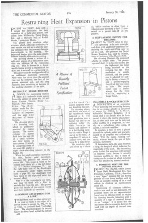
PATENT No. 591,871 deals with a means for restrainini the heat expansion of a light-alloy piston, and comes from Wellworthy Piston Rings, Ltd., and J. Howlett, both of Radial Works, Lymington, Hants.
The patent first mentions other schemes, which, although satisfactory in their results, are said so to alter the casting technique that the processes become impracticable in the foundry. The improved design gives the same results without creating difficulties in casting.
The drawing shows a section of a split-skirt piston or a well-known type, with the addition of the restraining ring (1). This is housed in a downwardly facing groove in the inside of the skirt, and is secured by a spring ring (2).
This groove can be easily produced by an additional machining operation. After wear has taken place, the control ring can be removed, the face of the groove skimmed out, and the ring replaced, thus permitting an increase in the working diameter of the skirt.
HYDRAULIC BRAKE BOOSTER
ADEVICE for multiplying manual effort in a hydraulic brake system forms the stffiject of patent No 592,419 from Empire Electric Brake Co., Newark, New Jersey, U.S.A. The chief claims made for the scheme are the rapidity of response and the ease and cheapness Of manu
facture. '
The drawing shows the boosting unit, which is preferably powered by engine suction. The master cylinder (1) pumps fluid into the end (2) of a small cylinder and first . moves an inner piston (3) which, by occupying some of the space (4), applies a
slight slack-absorbing pressure to the brakes (5).
When the small piston has moved to its limit, further pedal movement increases the pressure and moves a piston (6). This causes a valve to be opened and admit air to the left-hand side of a flexible diaphragm (7). As the right-hand "side of the diaphragm is permanently under engine suction from a pipe (8); The' diaphragm will then move to the right and assist the
• manual effort. • Pipe 9 is the atmospheric air inlet, and may be fitted with a filter to exclude dirt from the unit. The patent gives full details of the control valves and their methods of operation.
A SANDING ATTACHMENT FOR A LORRY
TO distribute sand or other substances on road or farm is the object or a device shoWn in patent No. 592,370, by A. Trent. 72, Golsmid Road, Tonbridge, Kent. The distributing gear is located below the floor level, so that the vehicle
A34
(6), whichreceives iis drive from a reduction gear driven by a shaft (7) connected to a power take-off on the gearbox.
A SELF-JACKING SYSTEM FOR TRACTORS
pATENT No. 592.175 refers to tractors operating n the unit principle, and deals with additional 'apparatus for
enabling the imple nent-lifting gear to act as a jack. The patentees are David Brown Tractors, Ltd., and H. Merritt, both of Meltham Mills, Huddersfield.' The drawing illustrates the proposed scheme in simple terms. The power operated shaft (1) is the one used to lift the implement, the latter being attached to the swinging bar (2). This 'mechanism is amply powered, and the power can be adapted for jacking by fitting a beam (3) and a ground-engaging foot (4) of the type usual in jacks. The patent covers also a similar scheme for the front w heels, employing a longer beam.
INAUDIBLE KNOCKS DETECTED A DESCRIPTION of an apparatus 171 for detecting and measuring detonation in an engine cylinder is described in patent No 592,362, by E. Dodds, Arborfield, Wantage, Berkshire. It is stated that if an electric wire be hammered, it alters the electric characteristics, so that each blow can be detected, either audibly in a telephone, or visually on a cathode-ray tube, using, of course, a suitable amplifier.
In practice, a loop of wire is placed around the cylinder under test, and connected to an amplifier and cathode-ray tube. With the engine running correctly, without knock, the .43cit of light remains stationary.
If detonation starts, the spot becomes a strip, the length of which indicates the magnitude of the shock. The interesting point is that this apparatus will indicate an incipiem knock before it actually becomes audible, Sc that a state of tuning can be arrived at which is better than that attained by normal methods.
A BOOSTING MIXTURE FOR PETROL ENGINES
PATENT 'No. 592.966, which comes from Shell Development Co., San Francisco, California, U.S.A., describes a new "dope" intended for use during periods of extra heavy loading, such as when an aircraft is taking off or a road vehicle is climbing an exceptionally .steep hill.
Mentioning the common additives, such as are used for anti-detonants, the patentee states that an usprecedented boost can be obtained from an engine by injecting into the induction pipe a quantity of a type of chemical known as an "amine." it is stated that the maximum effective quantity dare not be used with an engine of normal construction.