


CUTTING DOWN MACHINING COSTS
Page 38
Page 39
If you've noticed an error in this article please click here to report it so we can fix it.
By Using Modern Machinery, it is Possible to Obtain Higher Efficiency with the Manpower Available, Thereby Reducing Production Costs
I N the increasing application of centreless grinding to form work, difficult piece are occasionally encounte;ed which necessitate not only an accurate radius but, in some cases, a radius or arc to blend accurately with a taper or form Examples of such requirements in current motor-vehicle practice include steering ball-ends and knuckles, engine valves and ball-race tracks, all presenting awkward problems because of this need for a perfect blend.
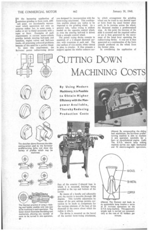
To meet this requirement, the Scrivener patent radius-truing device
was designed for incorporation with the form-truing attachment. This combination enables almost any radius to be imparted to the grinding wheel. As a general rule, -adius truing is seldom needed on the opposite control wheel, as even the steering ball-end is driven from a straight control wheel.
The patent truing device consists in essentials of a C-shaped diamond carrier, with trunnions at each end. The rear surface of this carrier, when viewed in plan, is circular. It thus presents a support against the similar concave sur face of the exterior C-shared base in which it is mounted, bearings being provided at the top and bottom of the carrier.
By means of a handle and adjustable gate, the carrier is movable through 180 degrees. This variable adjustment by means of the gate settings permits correction to be made to compensate for the varying relations of the face of the diamond to the centre about which the radius is struck.
The device is mounted on the barrel of the normal torm-truing attachment, by which arrangement the grinding wheel can be trued to any desired taper or form from the usual former plate until, in its traverse across the wheel, the diamond reaches a predetermined stop. At this point the traverse of the slide is arrested and the required radius or arc is then generated by the movement of the hand lever operating the radius-truing device. A true arc is thus generated as a continuation of the form already produced on the wheel from the former plate.
In considering the application of centreless or any other torm of precision grinding to the finish of a piece, one must observe several fundamental and commonsense points applying to radius truing. The attachment descried enables convex radii to be generated on a wheel up to in. or Up to 1 ins, concave radius.
Although it is possible to form a complete semi-circle, either concave or convex, it would be useless to do so, as the wheel would break down rapidly at the sides of the half-circle and the size would rapidly be lost at these points.
A further matter to be considered is the physical size, shape and position of the diamond-truing tool while this form is being generated. Obviously, at the conclusion of generating the half-circle, the diamond tool would not be in a position to make a longitudinal cut on the wheel, first, because of the interference of the holder, and, second, because the cutting facet of the diamond is no longer in position for applying a cut in this direction.
For these reasons, the emergence angle of the radius is largely a matter of compromise, and the radius that can be generated on the wheel would be. limited approximately to an are up to 90 degrees for a convex form, or up tr, about 120 degrees for a concave form.
The machining of profiles on components such as camshafts presents a problem which can be solved in two ways. First, one can use a tool housed on a rocking saddle, but this may have shnrtcornings in tool-cutting angles and only one lobe of the cam may be machined at a time.
This method, which has been the standard .procedure on the Continent, has been superseded by a British • comizerpart, which has been in use for nearly 12 years. British practice, which is exemplified by the Scrivener profile-turning lathe, is simplified by employing a series of tools carried on spring-loaded master cams operating on the tool holders. The tool in this case has a knife edge, and traverses the lobe of the cam, instead of operating in the former way, which employed a plunge cut.
For a six-cylindered engine camshaft the Scrivener machine would employ a toolbox which, operated from the master camshaft, would machine all 12 camshaft lobes in one operation. A camshaft for a four or six
cylindered engine can be machined in the same time, approximately 31 minutes being the maximum. The. former method would probably take 45 minutes, including the change-over period between machining each lobe.
Certain designs of camshaft in which the. cams are too closely spaced to permit the introduction of a tool between the pairs, !lily require the workpiece to be reversed and the machining to be effected in two operations. This method permits an infinitely. varied range of profiles to be produced, ranging from a circle to a flattened ellipse.
Both the centreless-grinder wheel truing attachment and the profile-turning lathe are products of A. Scrivener, Ltd., Tyburn ROnd; Birmingham.
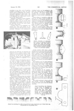
Another machine which plays a smaller, although just as important, part in the motor industry is the electric-lamp making machine. Such a machine, which produces the relatively small portion of the leads and spiral filaments, is now being manufactured in this country by the E.V.D. Engineering Co., Ltd., Belvedere Works, Cotswold Street, London, S.E.27, and its associate, the Dorset Engineering Co.
This machine carries out eight mechanical and 13 electro-magnetic operations to form each filament and holder. Each filament. consists of three wires—one of copper, which is soldered to the contacts, another of nickel which supports ,the filaments, and a third of copper-clad-nickel iron.
In the operation of the machine, the copper and nickel wires are fed forward to the desired lengths and gripped. The bimetal is cut to length and fed mechanically into a gap between the copper and nickel wire, where it is held. High-temperature flame jets are directed at the joint, and mechanical butting takes place at the fusion point.
The welded workpiece is then cut off and falls through a device for flattening and hooking the nickel end to form the filament mounting.