


Farm Tractor with Variable Front Track
Page 28
If you've noticed an error in this article please click here to report it so we can fix it.
New Ferguson Device by Which Frontas well (..s Rear-wheel Position can be Adjusted, in Respect of Track Dimension, Without Alteration of the Steering Setting
THERE is no doubt that •a variable track-width adds 1 greatly to the practical usefulness of an agrimotor. Hitherto, however, such variability has been mainly confined to the rear wheels and the front wheels have constituted at !east a minor limiting factor. Adoption of a like scheme for the front wheels as for the driving wheels leads usually to complications in the steering arrangements.
The problem has now been tackled by that enterprising tractor expert, Mr.. H. G. Ferguson, Belfast, who has produced a scheme whereby changes in the front track can be effected as easily as in the case Of the rear and without influencing the steering geometry.
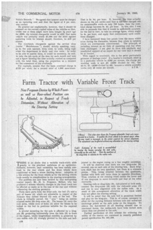
Three main parts form the front axle, the bed (7) and a pair of beams (9) which are adjustable in respect of the distance they extend beyond the ends of the bed. The whole is virtually curved, the " arcs " being on centres situated under the drop arms (6). The beams (9) carry the stub axles, whilst rows of holes (2) allow the beams to be bolted to the bed in positions suitable for the required widths.
A pivotal mounting for the axle is afforded' by a kingpin (8) projecting horizontally from the hole (3) in front of the engine, whilst longitudinal stability is preserved by two radius rods (5) strongly pivoted 'to the axle and ball
jointed to the engine casing on a line roughly amidships. It will be observed that there are two drop-arms (6) secured, one on each side of the steering box. Each drop.. arm shaft has its own quadrant, but there is a common pinion. This, being situated between the quadrants, meshes with both and turns them in opposite directions. Thus, rotation of the steering wheel causes the lower end of one drop-arm to move forwards and that of the other rearwards.
Steering rods or drag-links (6), ball-jointed at both ends, connect the drop-arms (6) with the stub-axle arms (1) and run in near alignment with the radius rods. As a result of this arrangement alteration of the track width does not affect the steering setting.
It will be noted that the axle bed is permitted limited end play on the king-pin. This is, of course, necessary to allow for the varying distance between axle and radius-rod anchorage points as the axle rocks on the king-pin. To relieve the last-named Of all bending stresses due to tractional forces, the radius-rods have wide forked ends where they are pivoted to the axle. Further particulars of .this scheme for widening the utility of the tractor are contained in recently published patent specification No. 541,220.