


Advanced Producer-gas Washing Plant
Page 23
If you've noticed an error in this article please click here to report it so we can fix it.
Liquid Cleanser and Gas Drying Apparatus Developed by "Eastern National's Chief Engineer
A S introduction to the following description of a producer
gas cleaning apparatus, for which Mr. W. J. Morison, chief engineer of the Eastern National Omnibus Co., Ltd., is responsible, we quote from the issue of this paper, dated October 4, 1940, Reporting a conference held by the Producer Gas Association, we outlined the experiences related by this producer-gas supporter.
Mr. Morison said that, having suffered heavy cylinder wear with fabric and coke filtration, he tried washing the gas with a water filter, and got water in the engine. This led to his developing a water separator. After two years of experimenting, which represented 5,200 miles, wear proved to be only 0.001 in. per 3,737 miles.
A patent was taken out as a result, and the specification (No, 541,533) has recently been published. The, foregoing certainly lends interest and conviction.
It is also worth recording that Mr. Morison expressed the opinion that, for the public-service vehicle, producer gas had come to stay.
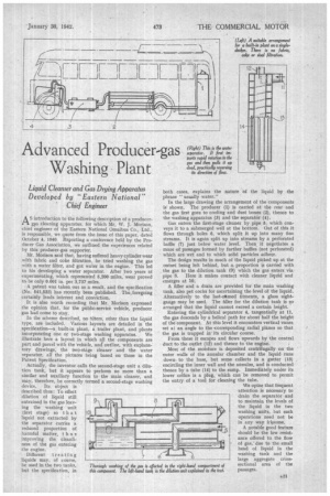
In the scheme described, no filters, other than the liquid type, are included. Various layouts are detailed in the specification—a built-in plant, a trailer plant, and plants incorporating one or two-stage washing apparatus. We illustrate here a layout in which all the components are part and parcel with the vehicle, and' outline, with explanatory drawings, the tsvo-stage cleaner and the water separator, all the pictures being based on those in the Patent Specification.
Actually, the inventor calls the second-stage unit a dilution tank, but it appears to perform no more than a similar and auxiliary function to the main cleaner, and may, therefore, be correctly termed a second-stage washing device. Its object is described thus: To effect dilution of liquid still entrained in the gas leaving the washing unit (first stage) so that 10 liquid not extracted by the separator carries a reduced proportion of harmful matter, thus improving the cleanliness of the gas entering • the engine.
Different treating liquids may, of course, be used in the two tanks, but the specification, in
both cases, explains the nature of the liquid by the phrase "usually water."
In the large drawing the arrangement of the components is shown. The producer (1) is carried at the rear and the gas first goes to cooling and dust boxes (2), thence to the washing apparatus (3) and the separator (4).
Gas enters the first-stage cleaner by pipe 5, which conveys it to a submerged well at the bottom. Out of this it flows through holes 6. which split it up into many fine streams. It is again split up into streams by a perforated baffle (7) just below water level. Then it negotiates a maze of passages formed by further baffles (not perforated) which are wet and to which solid particles adhere.
The design results in much of the liquid picked up at the outset being left behind, but a. proportion is carried with , the gas to the dilution tank (9) which the gas enters via pipe 8. Here it makes contact with cleaner liquid and emerges at 10.
A filler and a drain are provided for the main washing tank, also pet cocks for ascertaining the level of the liquid. Alternatively to the last-remed fitments, a glass sightgauge may be used. The filler for the dilution tank is so arranged that the liquid cannot exceed a certain height.
Entering the cylindrical separator 4, tangentially at 11, the gas descends by a helical path for about half the height of the component. At this level it encounters vertical vanes set at an angle to the .corresponding radial .planes so that the gas is trapped in its circular course.
From these it escapes and flows upwards by the central duct to the outlet (12) and thence to the engine.
Most of the moisture is deposited centrifugally on the outer walls of the annular chamber and the liquid runs down. to the base, but some collects in a gutter (13) encircling the inner wall and the annulus, and is conducted thence by a tube (14) to the sump. Immediately under its lower orifice is a plug, which can be removed to permit the entry of a tool for cleaning the tube.
We opine that frequent attention is necessary to drain the separator and to maintain the levels of the liquid in the two washing units, but such operations need not be in any way irksome.
A notable good feature should be the low resistance offered to the flow of gas,due to the small head of liquid in the washing tank and the large aggregate crosssectional area of the passages.