


GERMANY'S EQUIPMENT FOR
Page 26
Page 27
Page 28
Page 29
If you've noticed an error in this article please click here to report it so we can fix it.
iNNING ON GASEOUS FUELS THE desire in this country to reduce the use of petrol by employing gases and solid fuels has a parallel in the evolution which has been taking place in Germany during the past few years and, owing to the longer time of preparation—surely an anticipation of the present emergency—quite a number of efficient systems was evolved for the utilization of permanent gases, liquefied gases, and producer gas. Descriptions of some of these may be helpful to British engineers who are now confronted with similar problems.
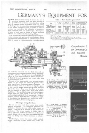
It is necessary to distinguish between permanent gases, such as coal gas, coke gas, marsh gas (methane), which can be stored in pressure bottles or cylinders up to about 2,850 lb. per sq. in. (200 atmospheres), and gases which can easily be converted into the fluid state and are then under constant vapour pressure during the emptying of the cylinders. This pressure is usually 28-210 lb. per sq. in. (2-14 ats.) according to the air temperature. In Table I the main properties and certain other data of these gases are given.
Because of the unfavourable ratio between cylinder weight and gas weight the radius of operation when using high-pressure permanent gases is restricted. Of more advantage seems to be the use of liquefied gases. In this case the weight works out at about one-third that of the other. They seem, therefore, to be better able to compete on more equal terms with normal liquid fuel. The special advantage of the liquefied gases is their good heat value, which, in the case of butane, can be as high as 2,830 B.Th.U. per cubic ft. Evidence of this is found in the fact that the long-distance flights of the airship Gras Zeppelin were carried out with a mixture of methane, butane and propane.
Advantages of Liquefied Gases
For use as motor fuel these gases have certain inherent advantages. All vaporizing difficulties are eliminated. Starting in very cold weather causes no trouble. The risk of oil dilution in the crankcase is eliminated. The 'octane number is higher than is usually obtainable, without special means, in the Case of petrols. Mixed with air, the gases have a wide explosion range and finally burn without residuum or offensive smell.
Disadvantages, besides the extra weight entailed, include a reduction in power output which, in the case A24
of marsh gas and coal gas, amounts to a loss of about 10 to 20 per cent, as compared with petrol. However, in the case of butane and propane, the same output as petrol can be expected. With producer gas, on the other hand, the loss is greater, being usually well up on the above-mentioned figure.
Before dealing in detail with thd necessary equipment, the matter of additional dangers and risk should be considered. Extensive trials, in particular with used bottles, have shown that traffic is not more endangered by a possible explosion of the pressure cylinder, than, for instance, by the danger of the burning of the petrol tank (a risk that does not exist, of course, on oil-driven vehicles).
However, every part of these plants has to be manufactured and inspected with the greatest possible care, regardless of the extra cost involved. Among necessary precautions usually demanded by the authorities are that no gas pipes should be conducted through the driver's cab cr passengers' compartments, unless protected by cover tubes in connection with the open air. Manometers must be equipped with throttling devices, so that full pressure shall not act on them. The pipe connection with the botfie has to consist of a pressure-resistant, gas-tight rubber hose, which, in the case of fire or excessive pressure, would be easily destroyed to allow the escape of gas to the open air. Bottles have to be provided with a safety device (crackplate). The bottle valves have to remain open during service and can be operated only from the stop valve in the driver's cab. Further, the driver is advised to use only one bottle at a time when a number of bottles is coupled together. The valves should not be closed before the emptying of bottles is completed.
Use of Gas Officially Encouraged To encourage the use of gaseous and solid fuels, the German Government, several years ago, reduced the taxes by about 50 per cent, for new vehicles and by between 50 and 75 per cent for conversions, the higher reduction rates applying for heavy loads. As the bottles usually remain the property of the gas supplier, no extra costs for these are involved. As only big concerns
are the suppliers, standardization of bottles and, in consequence, easy exchange from chassis to chassis is possible. In connection with this is the main problem of providing sufficient filling stations in bigger cities, for, in consideration of the limited radius of action of these vehicles, additional miles to and from the filling stations are absolutely prohibitive.
For permanent gases in Germany only the high-pres sure system is in use. Owing to the high initial pressure of the gas two pressure-reducing stages are considered necessary, as the pressure in the cylinder changes with different degrees of filling. Usually the first stage is adjusted for a constant over-pressure of 7 lb. to 42 lb.
per sq. in., and from this it is brought down to that of the atmosphere. Usually the regulator valve is opened by the vacuum pressure of the motor. For the introduction of the gas into the engine combustion chamber, as well as for the mixing of the gas with air, the possibility exists of using the air pipe of the carburetter, by providing separate ports and a pipe connection, or to use a special device for this purpose with its own inbuilt throttle control (see Fig. 5).
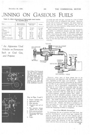
Fig. 2 shows schematically the arrangement of a highpressure gas plant on a lorry. The cylinders, in this case, are arranged crosswise to the main frame members on top of the frame girders, but they are also sometimes placed alongside of the main frame members. No part of a bottle should project and special care has to be applied to secure a safe support for the bottles in brackets, for preference by cushioning bolsters.
General Layout of the System The pressure pipes from the bottle valves lead to a main pipe, one end of which serves for the filling and is equipped with a valve for this purpose. The main pipe leads to the main valve in the driver's cab and a branch leads to the high-pressure manometer. From the main valve the gas is conducted to a two-stage pressure regulator and is reduced to atmospheric pressure. Thus the gas is sucked by the motor and mixed with air ore its way. There is a separate pipe for idle running. In some systems a preheating device is included between the manometer and the reducing valve, and there is a second manometer in the low-pressure system between the high and low-pressure reducing valves.
Fig. 3 shows the arrangement of a plant for liquefied gas in which two gas bottles are used. In this case, the pressure regulator has to be provided with heat-radiating ribs and two main valves, one for each bottle, have to be installed. From these the gas passes through a preheater A26. coil before entering the pressure regulator. To avoid a burst cylinder, in the case of an accident, over-pressure safety devices, in the form of crack-plates, are arranged at the ends" of pipes leading to the roof of the driver's cab.
In connection with pressure regulators for liquefied gases the following four main considerations are noteworthy :— The gas is taken from the cylinder or bottle in a fluid state. Therefore, during the whole emptying time of the cylinder, it is under the constant vapour pressure of the fluid.
For the vaporization of the fluid, some amount of heat is necessary which has to be applied to the gas from the outside.
Adjustment to Minimum Vacuum.
The pressure-regulating valve has to be adjusted to the lowest vacuum (slow rotation of the crankshaft when the motor is being started) and, during the entire range of speed and load, the regulator has to adjust itself to a vacuum pressure which must be as low as possible.
The pressure regulator valve has to be closed gastight when the motor is not running.
These conditions are met, in a simple and effective way, by the pressure reducers, which will now be described.
The BV-gas regulator (Fig. 7) consists of a chamber. for relieving the pressure and for vaporization, to which the fluid gas is led by means of a valve controlled by the vacuum of the motor in such a way that the valve is held closed so long as the motor is stopped. The valve is
connected by a lever system with the diaphragm. The lever and diaphragm are so designed that the valve opens at a minimum vacuum pressure. The same lever system also actuates the closing spring of the valve, so that when the vacuum disappears (when the engine stops) the spring exerts its full force on the valve which, therefore, closes gaS-tight. The pressure of the spring is controlled by an automatic balancing device, shown on the upper right-hand side of the illustration. The oil-pressure of the engine acts on a small diaphragm, supported by the head of a spring-loaded piston. The free shaft end of the latter acts on the end of a spiral spring and gives to this the necessary pre-load.
For the necessary pre-heating of the gas, the bottom part of the regulator is funnel shaped and provided on
the lowest point with a closed pipe in the stream of exhaust gases. Thus the heat supply starts so soon as the engine fires. Any liquid not immediately vaporized, accumulates in this pipe extension, from which gas rises and mixes with new cold gas again, communicating heat to the gas flowing from the relieving chamber to the induction pipe.
For this reason the regulator has to be mounted directly on top of the exhaust pipe. Another possibility is to utilize the neat of the cooling-water system for heating the gas before it enters the pressure regulator (see Fig. 7).
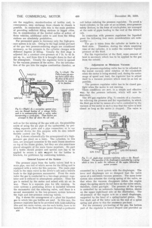
Fig. 4 shows the Hessenwerk two-stage regulator, which can be utilized for both high-pressure (permanent) as well as liquefied gases Gas enters the pre-chamber through a valve controlled by a diaphragm and a spring, where it is reduced to about 14 lb. per sq. in. Then it enters a second chamber, similarly built but of
extended dimensions, owing to the larger gas volume, and is sucked thence into the induction pipe. Heat is
applied, in this case, either by means of a pipe coiled around the pressure pipe or only by radiated heat from the exhaust pipe.
In the lower part of Fig. 5, the air-control valve is shown. The purpose of this is to supply the engine at any speed with the correct gas-air mixture. ,This valve is fixed to the air-inlet of the carburetter. The head, loaded by fine adjustable springs in both directions, is operated by the vacuum. Owing to the venturi, a definite ratio is maintained between the air and the gas. Volume of gas can be controlled by a metering valve in the form of an adjustable throttle.
Water-heated Vaporizing Chamber
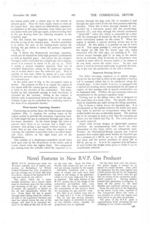
Functioning on similar lines, the PalIa-Leuna two-stage regulator (Fig. 1) employs the cooling water of the engine system to provide the necessary vaporizing heat. In both stages the gas is conducted through pipe coils in hot-water chambers. In the latest design the valve is opened when there is no vacuum, but a slight overpressure, thus giving a gas supply without suction. In order that no gas may escape when the engine is not running, the regulator is provided with a so-called standstill Valve (shown on the right hand side of the illustration).
This consists of a diaphragm-controlled cut-off valve held open only by the oil-pressure of the motor, and of course closed when the engine stops. The compressed gas coming from the cylinder enters the vaporizer at A, streams through the pipe coils (B) in chamber C and through the open valve D into the first pressure-relieving chamber. From this it flows through channel E, surrounded by a hot-water jacket into the second-stage chamber (F), and then through the already mentioned "
stand-still" valve (G) which is connected by a stem with the diaphragm H loaded by the oil pressure of the motor lubrication system via the union V. When the engine is started, a special starting device has to be actuated. By this piston J is pressed on top of valve seat K. This opens passage L, and gas flows through the starter jet (M) into the starter pipe (N), being connected with the inlet pipe, air entering at V. Gas cannot escape through pipe 0, so long as the starter device is actuated, even if already an oil-pressure were created to open valve G, because piston J, by means of
its cup form, covers the whole valve. In any case piston J must be lowered sufficiently to prevent the leaking of gas and the production of too rich a mixture.
Improved Heating Device
The Solex two-stage regulator is of similar design, except for the fact that in front of the regulator a heating coil is arranged which has to be conducted along the exh3ust pipe. A later model, however, is equipped with a special pre-heating device standardized for all types of engine, so that heating coils of special construction can be dispensed with. Further, the gas metering valves are incorporated in the pressure-regulator body.
Turning now to the filling valve, this is designed on the usual lines of a screw valve. The spindle, However, must be absolutely gas tight during the filling operation.
Fig. 6 shows a safety device for liquefied gas. It is A incorporated in the system between the bottle and main stop valve to prevent an overpressure when the thinwalled bottles become accidentally heated. The opening has to be arranged in such a way that the escaping gas blows over the vehicle (see Fig. 3). The crack plate can be easily replaced.
There exist several designs of lightweight pressure cylinders. An accompanying table shows the main dimensions of two types which are eitensively used. Further, the Rheinmetall-Borsig concern has evolved seamless thin-walled light-metal bottles for liquefied gas for a pressure of 1,100 lb. per sq. in. (80 atmospheres) and more and for service pressures of about 700 to 850 lb. per sq. in. It is to be expected that by*ineans of such bottles the weight ratios given in Table I can be considerably reduced.