


SAVING WEIGHT ON BUS BODIES.
Page 10
Page 11
Page 12
If you've noticed an error in this article please click here to report it so we can fix it.
A Detailed Description of the Means Employed to Keep the Weight of the K-type Body Within the Required Limits.
THERE ARE FEW people who realize what great difficulties the London General Omnibus Co. have had to contend with in order to build an omnibus, which, whilst meeting all the requirements of the police, at the same-time, carries 12 more passengers than the B-type bus with which we are all so familiar. The problem did not merely include lightening the chassis; it also included the provision of a body for thegreater passenger-carrying capacity which had to be of ample strength and yet lighter construction. Wehave already dealt with the construction of the K-type bus chassis, and in this article we will deal with the methods by which the K-type bus betty has been constructed.
The• new body, though of larger capacity, is actually over 2 cwt. lighter than the old standard body, and many were the pessimistic criticisms levelled against it by conservative members of the coachbuilding trade. In spite of the criticisms, two of these bodies have been running most successfully on services Nos. 11 and 25. Of these, No. 25 service, from Victoria to Seven Kings, is a very severe test, as it includes some of the worst roads in the neighbourhood. The K-type on this service has been in operation four months,. and up to the present not the slightest movement in the framework of the body has been observed.
The new body is the result of an efficient co-operation between the chassis builders and the body builders. It can hardly be considered as an entirely coachbuilding job ; it is more like a combination of coachbuilding and engineering.
The main principle adopted in the construction of the body is the utilization of the longitudinal strength of the chassis frame as a base for the body. Previous bodies were built so that they were rigid in themselves and did not have to depend upon the frame of the chassis for their strength ; this, of course, necessitated heavy construction. The new body, when apart from the chassis, has very little strength in the longitudinal direction, and during its construction it is always supported by a stout framework, which is practically a model of the chassis frame. In the old models, the back platform and step were -carried by the body itself, and this necessitated the use of strong irons at the back in order to take the leverage exerted by passengers standing on the step,
platform and staircase. In the K-type bus the chassis frame has been extended to carry this platform and also the step ; leverage having been thus removed from the wear portion of the body. the crossbars and side pillars u32 have been made much lighter, and the irons have been dispensed with.
Previous efforts to lighten the bodies designed for bus work were confined to cutting down heavily-constructed bodies in order to make them light. IC was found that this method did not prove satisfactory, in the same way as it is difficult to cut down-the weight of a chassis, without redesigning it, by removing metal from the various units.
Thb latest method of construction is to make the body extremely light and then to strengthen the various components where this is found to be necessary ; this method is far more scientific than the other and tends to equalize the stresses on the various portions. A considerable amount of strength is added to the roof, without increasing its weight, by " tubbing" it for one inch in its length ; this is, of course, in addition to the 3-in, compass allowed on the width. " Tubbing " makes the roof somewhat similar' in shape to the staves of a barrel, though naturally the curvature in the longitudinal direction is very slight. Practically all the panels of the body and also the advertisement boards are constructed of three-ply, water-proofed birch, which is to Air Board specification. One of the tests to which samples of this three
ply ''wood are subjected is to boil it in water for 12 hours, when the plies 'Must pot separate.,
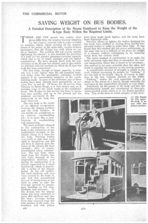
For speed and accuracy in building, the top portion of the body is constructed on a jig which is a duplicate of the tops of the pillars of the bottom portion of the body on which the top half of the body has to rest, and to which it is fixed. When -completed, the top half is lifted on to the other portion of the body and held in position by ordinary coachmakers' wooden pins, and by steel gusset plates.
The crossbars,. side pillars, and hoop sticks are all cut through their centres and provided-with inserts of 15 S.W.G. mild steel, and at each corner a 14 S.W.G. steel gusset plate is provided. When the two halves of the bus are in position, these gusset plates connect all the steel liners and completely encircle the bus -with bands of steel. The steel and. wood are held together by ordinary wood screws, the plain portions of the screw shanks.passing through holes drilled in the steel.
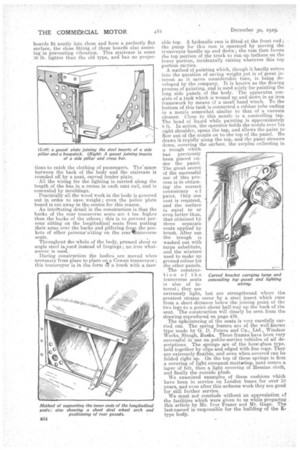
The bottom gussets are almost hidden from view by the seats. One of the drawings -which we reproduce shows a gusset under one of the two longitudinal seats. The top gussets are concealed by artistically. carved brackets, which also serve to conceal the wiring of the lamps and to carry the lamps themselves. The bracket sides are also of three-ply .• The roof is additionally supported by l'O'fir tubular • brass pillars.. The two hack pillars are supported on ... crossbars, the forward pair being bolted to the floor between crossbars; blocks are placed under the floor
dy between it and the chassis frame in order to take the
downward pressure.. The pillars are also attached rng for stde panels. n its jig. (3) How transveyor. 14) A
r details. (5) The totter view from the
to the backs of fourof the seats, which both strengthens these backs and lessens vibration.
The roof is, constructed hi two thicknesses of On. board, with waterproofed khaki duck between them. The wearing slats on the top of the body are made into mats, steel cross-pieces being screwed at the ends of the slats; these cross-pieces being themselves screwed to the floor_ By this construction the number of screws used for the slats has been reduced from 360 to 36; previously, when each slat was screwed down independently, the screws used to work loose and cause leakage into the interior of the roof. The old types half-round, forged steel side rail stanchions have been replaced by stanchions construcied of angle steel, to which are welded concave T-Weces to carry the tubular aluminium side rails. At the bottom corners the stanchions are strengthened by small angle-pieces welded into position, and on the exterior of each stanchion is welded a small bracket which carries the wood sideboards, as the latter have to support the inner ends of the top transverse seats.
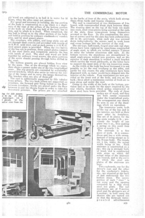
As the width of the body has been increased it is not possible to let the roof overhang at the sides, and partly for this reason the side* ventilators have been dispensed with, as water would have dripped into the interior of the vehicle. Four ventilators are now provided at the front end of the body, and two at the back ; these allow aoontinuous current of fresh air to pass along and under the roof. Owing to the width of the body at the bottom, provision had to be made for the space required by the rear wheels, therefore wheel arches constructed of sheet steel have been provided. The ends of these arches are of wood, and they are both neatly• concealed under the longitudinal seats. The arrangement can clearly be seen in one of the drawings which we reproduce.
The transverse seats, both atIthe top of the bus and in the interior, are held at their inner sides by footplates. The set of 24 plates for the top seats weighs l lb. ; previously the weigh of one plate was 5 oz. thus making a saving on this small item alone of nearly 7 lb.
The staircase is a fine piece of work. It is commodious and has a wide sweep, instead of being abrupt as in the B-type body. The treads are 2 ins, wider, the actual width being 18 ins. Each staircase is constructed on a jig ; this jig is strongly built of wood, and is constructed with steps on which the actual steps of the staircase are located, and to the curve of -which the steel side plates of the staircase are bent.
Two cupboards, one for the driver's coat and the other for the conductor's tickets, etc., are situated at the back of and underneath the two bottom steps. The centre portion of each " riser !' is cut away and the opening concealed by a thin sheet steel toe plate. The rail stanchions are of T-section steel and the stringers are of L-section ; in both cases the shorter ribs are turned out so that the three-ply waterproofed advertisement
boards fit neatly into them and form a perfectly flat surface, the close fitting of these boards also assisting in preventing vibration. This staircase is some 36 lb. lighter than the old type, and has no projec
tions to catch the clothing of passengers. The'space between the back of the body and the staircase is rounded off by a neat, curved fender plate. All the wiring for the lighting is carried along the length of the bus in a recess in each cant rail, and is concealed by mouldings. Practically all the wood work in the body is grooved out in order to save. weight ; even the police plate board is cut away in the centre for this reason.
An intel'esting detail in the construction is that the backs of the rear trans.verso seats are 4 ins, higher than the backs of the others ; this is to prevent persons sitting on the longitudinal seats from putting their arms over the backs and pilfering.froD the pockets of other personsKsittingon the rear transverse seats.
Throughout die -whole of the body, pressed sheet or angle steel is used instead of forgings ; no iron whatsoever is used.
During construction the bodies are moved when necessary from place to place on a Cowan transveyor ; this tranaveyor is in the form a a truck with a molt
able top. A hydraulic ram is fitted at the front end ; the pump for this ram is operated by moving the transveyor handle up and down; the ram then forces the top portion of the truck to run up inclines on the lower portion, incidentally raising whatever this top portion carries.
A method of painting which, though it hardly enters into the question of saving weight yet is of great interest as it saves considerable tune, is being developed by the company. It is known as the flowing process of painting, and is used solely for painting the long side panels of the body. The apparatus consists of a tank which is wound up and down in an iron framework by means of a small hand 'winch. To the bottom Of this tank is connected a rubber tube ending in a nozzle somewhat similar to that of a vacuum cleaner. Close to this nozzle is a controlling tap. The head of liquid while painting is approximately 8 ft. In action, the operator holds the nozzle over his right shoulder, opens the tap, and allows the paint to flow out of the nozzle, on to the top of the panel. He draws it rapidly along the top, and the paint streams down, covering the surface, the surplus collecting in a trough which hag previously been placed under the panel. The great secret of the successful use of this process is in obtaining the correct consistency o f paint. Only one coat is required, and the surface is equal to or even better than, that obtained by three separate coats applied by brush. After use the trough is washed out with turps substitute, and the mixture used to make up ground colour for the other panels.
The construction of the transverse seats is also of interest; they are extremely light, but are strengthened where the greatest strains occur by a steel insert which runs from a short distance below the joining point of the two legs-to a point about half-way up the back of the seat. The construction will clearly be seen from the drawing reproduced on page 479.
The upholstering of the seats is very carefully carried out. The spring frames are of the well-known type made by G. D. Peters and Cp., Ltd.' Windsor Works, Slough, Busks. These frames have been very successful in use on public-service vehicles of all descriptions. The springs are of the hour-glass type, held together by clips and edged with fine rope. They are extremely flexible, and even when, covered can be folded right up. On the top of these springs is first a covering of light c000anut mattiring, next comes a layer of felt, then a light covering of Hessian cloth, and finally the outside plush.
We examined examples of these cushions which have been in service on London buses for over 10 Tears, and even after this arduous work they are good for still further service.
• We must not conclude without an appreciation of the facilities which were given to us while preparing this article by Mr. Ivor Fraser and Mr. Gage. The last-named is responsible for the building -of the K. type body.
Carved bracket carrying lamp and concealing top gusset and lighting wiring.