A Dual-purpose Oil Filter
Page 48

If you've noticed an error in this article please click here to report it so we can fix it.
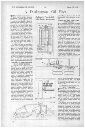
WHEN an engine is new there is no Vir doubt that the full-flow system of oil filtration is the beSt, because at that time the proportion of foreign matter Is probably at its greatest. When the engine has been well run-in, the partialflow system is mote suitable, and to . combine the two duties in one unit is the object of a design shown in patent No. 577,510, by the AC.-Sphinx Sparking Plug Co., Ltd., Dunstable, and others. The feature of the design is a quick change-over for either system.
Referring to the drawing, for full-flow operation the oil enters at port I, passes up pipe 2, and floods over the top of the filter pack (3). The cleaned oil assembles in the central chamber, and when it .reaches the level of holes 4 it flows hit° thc central tube, whence it reaches the exit (5).
To adapt the unit to partial-flow action, washer 6 is changed for another; this is shown in half-section at the point 7. A well (8) in the new washer allows most of the oil to proceed directly into the central tube • without having to pass the filter. Some does, of course, pass through, the proportion being determined by the size of a metering orifice (9) which leads to the crankcase. A safety vale (10) can shortcircuit the unit if it should clog sufficiently to raise the pressure appreciably.
TORSION-BAR SUSPENSION FOR MULTI-AXLED VEHICLES ADESIGN for a suspension system suitable for heavy multi-axled vehicles, comes in patent No. 577,425, from the Hickman Pneumatic Seat Co., Eden, New York, U.S.A. The arrangement not only provides the usual upand-down resilience, but also gives a measure of nexibility in a longitudinal direction, which assists cornering.
Referring to the drawings, each axle end is fitted with a cranked arm (I), which is 'hackled to a second arm (2); rubber bushes are used throughout. The second arm is fixed to a torsion-rod (3), which lies in an angular position in relation to the frame. The other torsionrod lies at a slightly different angle, so that they meet at a box (4). This contains a pair of meshing pinions, one on each end-rod, the.function of which is to provide a compensating action.
It is claimed that, when cornering, the two axles can assume a slight angle to each other—in other words, they have a self-steering action. This ensures true rolling motion on curves and prevents tyre-scuffing; at the same time, it will accommodate slight differences in tyre , sizes.
SURFACING SOFT STEEL WITH HARD ALLOYS
THEprocess of carburizing, by which soft steel can be given a hardenable skin, is welLknown, but it is, as its name implies, limited to the addition of carbon to the iron base. An extension of this process, by which a coating of any high-grade steel may be formed on the work, is described in patent No. 577.504 by Metals Interchange Syndicate, Ltd., and others, 6, Borough High Street, London, SEA.
Taking one example, mild steel was placed in a refractory tube with some pieces of ferro-tungsten. It was then heated in an electric furnace to 1,150 degrees C. and held for two hours, dur. ing which time a current of air, laden with chloroform vapour, was passed' through the tube. Upon examining the test-piece, it was found to have acquired a sharply defined outer layer of tungsten alloy; in other words, it had become surfaced with high-speed steel.
The. process is equally suitable for diffusing other useful metals into iron, such as nickel, manganese, vanadium, and cobalt, to name only a few. Each metal requires a special atmosphere for its diffusion, and the patent gives full details of these.
AN AMERICAN COUPLING FOR HEAVY TRACTORS DATENT No. 577,234 comes from a prominent American concern and discloses a means for coupling a tractor to a soil-working implement. The patentee is R. G. LeTourneau Inc., Peoria, Illinois, U.S.A. The scheme applies to large two-wheeled tractors and the object is to permit the tractor to turn sharply without fouling the implement.
The drawing shows the assembly, the size of which can be judged from the proportions of the driver's cab (I). The implement is attached to the tractor through the medium of a sturdy arched member (2), which is arranged to clear the tractor wheels in all steering positions. The arch is supported on ball joints at top and bottom, whilst a tension bar (3) transmits the bulk of the force to a strong triangulated framewcfrk (4)at the front. The soil-working tool can be raised or lowered by cables (5) worked by a power-driven winch (6).


