


THE SEARCH FOE SUSPENSION EFFICIENCY
Page 28
Page 29
Page 30
If you've noticed an error in this article please click here to report it so we can fix it.
be included, for, as previously shown, this can have an injurious effect on the suspension. Having determined an S. ratio for one vehicle, it may readily be compared with any other, regardless of the type of spring employed.
Further, from a simple graph it can readily be shown that, with hard suspensions and an S value of the order of 0.4, a small increase in spring deflection will permit of a corresponding softening of the springing. With values of 0.1, however, the limit of softness is approached, as big increases of static deflection are required to obtain quite a small improvement. One private car, to the writer's knowledge, has a suspension system which approaches the ultimate in this respect, a goal which is reached without difficulty, although to obtain good handling qualities at the same time is another matter.
It will be apparent that, with orthodox suspension, the spring rate remains constant throughout the range of loadings. Consequently, riding comfort must deteriorate when less than the maximum number of passengers is carried, and the most satisfactory vehicle in this respect will be the one in which the ratio of laden weight to unladen weight is the lowest. For instance, a vehicle on which the whole weight of the passengers is whereas, of course, in practice, the problem is complicated by the necessity of employing four-point suspension. Thus, when the front axle is moved in an upward direction after passing over a road bump, the body is disturbed, causing it to vibrate with pivoted motion about the rear axle. The same bump must, however, be traversed by the rear wheels, so that they, also, will cause body vibration, this time the swing being about the front axle.
In the event of the speed and the wheelbase of the vehicle being such that the time taken for the front and rear axles to pass over the same undulation finds the front end of the body on the down swing and the rear end moving upwards, pitching conditions will have been created.
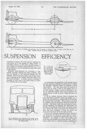
For ideal results, the road speed, wheelbase, and front and rear frequencies would be so chosen that the front and rear ends of the vehicle moved up and down in unison. However, more important requirements dictate the wheelbase, and for optimum riding conditions the speed may only, be assumed to be near 30 m.p.h. Below that speed conditions worsen to some small extent: in fact, below 30 m.p.h. a few bumps would cause violent pitching (Fig. 1).
Although small modifications may be made in the
suspension to improve the front and rear phasing, this must always be at the expense of riding comfort, as everything is done to use the softest possible springs, so that variation in frequency, being dependent as it is on spring deflection, must be obtained by using stiffer front or rear springs.
Hydraulic shock-absorbers are invaluable in that, without materially affecting the riding conditions, they may be adjusted so that improved phasing may be obtained. This is because the greater part of their resistance is obtained on the rebound, when their effect is not felt by the passengers A certain amount of pitching is inevitable at some part of the speed range, no matter how excellent may be the design. In consequence, the disposition of the sprung masses becomes important, although on public service vehicles the passengers' positions cannot be adjusted to effect improvement, The only large mass, the position of which may be varied, is that of the engine, but it is doubtful whether a designer would be influenced to use, say, an under-floor engine, unless such a departure was already settled, in order to secure a slight alleviation of pitching.
It will be realized, however, that to minimize the body disturbance caused by either axle passing over a bump, the load should be concentrated as far towards the extreme ends as possible. Such a course, if it could be adopted, need not necessarily affect the weight distribution. The desired result may be obtained by reducing the wheelbase, but although this undoubtedly has the effect of reducing the initial shock, closing the spring base towards the centre must lower the resistance to pitch when once instigated Further, the greater the spring base the lower will be the angle of pitch.
' In the case of orthodox suspension systems, wheelbase and spring base are equal, but certain types of suspen • sion permit of a spring base greater than that of the wheelbase. An example is that with trailing arms at the front and leading arms on the rear axle. Such a layout, when used on a chassis having a wheelbase of normal length and with the masses spread as far as possible towards front and rear, probably represents the ultimate that has been reached in vehicle-suspeilsion design (Fig. 2).
The wide spreading of the mass reduces shock in a pitching sense, the long spring-base reduces pitch angle, and the incorporation of hydraulic shock-absorbers is sufficient to control the tendency to prolonged fore-andaft vibrations.
The Effect of Bumps
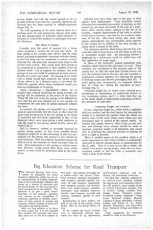
Consider, now, the result of passing over a bump which produces a vertical rise of only one wheel. At high speeds it has already been shown that the body inertia precludes sympathetic movement with the wheels, so that the body may be considered to remain vertical, although the axle beam has assumed some angle to the normal road surface. This causes both road springs to be compressed in proportion to their distance from the affected wheel. Let us suppose, for instance, that both springs of one axle could be positioned in some manner directly over each road wheel. The passing of one wheel over a bump would thus compress the spring immediately above it by a distance equal to the wheel lift, whilst the opposite wheel, being unaffected, would produce no compression of its spring.
Again, considering a hypothetical vehicle, let us imagine that, without modifying the spring strength, the springs will be positioned at the centre of the chassis. Wheel lift will now cause the springs to be deflected by only half the previous amount, but as two springs are compressed the sum total of spring resistance remains the same.
In practice, the springs are separated by a distance equal to approximately half the track, so that wheel lift must cause compression of the two springs to the extent of ona-third and two-thirds respectively of that of the displaced wheel, once more giving a total resistance to axle tilt equal to one spring placed directly above the wheel (Fig. 3).
Roll is, however, resisted in increased measure by greater spring spread, so that every possible device should be employed to take advantage of this fact, particularly for the renson that comfort is not reduced by such measures. With the orthodox laminated springs the limit is set by the necessity of wheel clearance when on lock. The employment of coil springs as resilient members, however, would permit their being more widely spread, as they could be positioned close to the brake drums Anti-roll bars have been used in the past to limit angular body displacement. These invariably consist of torsion bars mounted transversely, in bearings, so that vertical up and down movement of the axle, in a tramlatory sense, merely causes rotation of the bar in its journals. Angular displacement of the body in relation to the axle is, however, restricted by the torsional resistance of the bar. One-wheel bumps also cause such angular displacement. and, consequently, being opposed by the torsion bar in addition to the main springs, an undue shock is passed to the body.
The customary practice when fitting anti-roll bars is to crank the ends to form levers, and link these to the axle by universally jointed rods. An interesting scheme is employedon a well-known small car which may well find application on larger types.
In place of the universely jointed connecting rods, members rigidly fixed to the axle beam are used These members are articulated to the cranked ends of the torsion bar, so that the arms thus formed convey not only the torsional load to the bar, but also function as longitudinal reaction members for relieving the springs of braking torque and thereby prolonging their life. A softer spring may, consequently, be employed without fear of "wind up" during the operation of heavy braking (Fig. 4).
Unsprung weight has, in recent years, received great prominence as representing an undesirable feature of any suspension system, and it is often held that one of the major objects of independent suspension is that of the reduction of such mass.
Unsprung Weight and Comfort
In fact, unsprung weight has, within limits a negligible effect on comfort, and the chief reason for reducing this weight is to minimize the periods when the wheels are thrown clear of the road, which causes wheel spin and momentary lack of control of the steered wheels. At normal road speeds, however, these faults are not serious, and although every attempt should be made to maintain unsprung weight at its minimum, this would only be following the accepted practice of keeping all parts as Light as possible.
There is another aspect of this problem which is of some importance in that riding comfort is undoubtedly increased by heavier sprung masses, as demonstrated by the SR ratio. Thus it is truer to say that a better ride results from greater sprung weight, rather than by lower unsprung weight, in that the latter is beneficial only when it leads to the former.