


A New Leyland Combustion Chamber
Page 46
If you've noticed an error in this article please click here to report it so we can fix it.
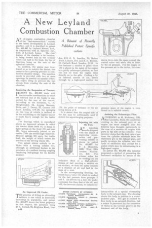
AN oil-engine combustion chamber of the last-moment-kick" variety is the latest development in Leyland practice, and it is described in patent No. 431,887 by Leyland Motors, Ltd., in conjunction with H. Spurrier, Jnr.,
both of Leyland, Lancs. The chief • feature of the chamber is its location, it being formed half in the cylinder block and half in the head, the line of bisection being on the axis of the spherical chamber.
In addition, the piston may overtravel so as to restrict the throat; this seems to be a growing practice in cornhustion-chamber design. The injection nozzle is provided with two or more openings,"or possibly an annular orifice, the object being ..sto prevent the fuel stream from crossing the axis of the chamber.
Improving the Suspension of Tractors.
PATENT No. 431,690 deals with tractor-trailer combinations in which the forward end of the trailer is supported, by the rear of the tractor. According to the inventors, G. H: Hooghwinkel, 54, Avenue Marceau, Paris, and J. Davey, 27, Cannon Hill Lane, London, S.W.20, the springing on this type of vehicle is inclined to be too unyielding to the lighter tractor if made heavy enough for the trailer load.
The drawing which is reproduced shows an improved scheme in which the tractor frame itself (1) is hung on light springs at the front (8) and rear (6), being universally jointed at the centre (7) to the trailer bogie frame (2). Heavier springs (5) carry the trailer load, the weight of which assists the traction of the driving wheels (4).
This patent relates entirely to vehicles with a towing column (3), although an additional feature is the provision of a resilient towing coupling employing leaf-springs for its flexible member.
An Improved Oil Cooler.
TiIEpractice of fitting an oil-cooling radiator is one which is deservedly increasing in popularity, and patent No. 431,677 shows the latest proposals in this respect, the patentees being D. A. Corteel, 67, Rcighton Road, Lon
B40 'don, E.5, G. D. Smedley, 78, Nelson Road, London, N.8, and R. H. Rhodes, 18, Fairholt Road, London, N.16. In this instance a number of gilled tubes (3) is placed in the sump of the engine in a partly submerged position, so that the hot oil from the engine drips directly on to the gills. Cooling is by an internal current of air, drawn through by a high-speed suction fan (1), the point of entrance of the air being shown at 2.
It is stated that the output side of the fan may be additionally used if desired for supercharging purposes.
Injecting Air with the Fuel.
ANinjection nozzle designed with the object of improving atomization and preventing dribble is shown in patent No. 431,657 by P. J. Reynolds, 3269, West 24th Avenue, Vancouver, B.C. The scheme relies for its working on the inductive effect of a high-velocity stream of fuel exerting a suction on an air-duct, so that the spray consists of a mixture of air and fuel in the form of a mist.
In the accompanying drawing, the nozzle has a valve (1) which is worked by the fuel pressure from passages 2 and 3. Air arrives via a duct (4) under a pressure less than that of the oil, and will, the inventor claims, be inductively pression space of the engine is mentioned as a suitable source.
Assisting the Exhaust-gas Flow.
A CCORDING to M. Kadenacy, 120, 1-1Rue Lecourbe, Paris, the conditions existing in the exhaust port of an engine are more complex than has hitherto been thought, particularly in the case of a modern oil engine with ports in tbe side of the cylinder. This inventor states that the first rush of gas from the cylinder rebounds from the stationary gas in the exhaust pipe, and partly re-enters the cylinder, and this cycle of oscillation may persist for a period which may be embarrassing in a high-speed engine.
In patent No. 431,857 this inventor propounds a method of preventing the backward oscillation by means of the interposition of a special obstructing body in the exhaust pipe. The drawing shows this body in position in a waterjacketed pipe. The gas is claimed to flow freely in an outward direction, but a return is prevented by the formation of eddies in the toroidal grooves in the rearmost end of the body,