


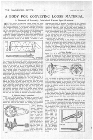
A BODY FOR CONVEYING LOOSE MATERIAL.
Page 62
If you've noticed an error in this article please click here to report it so we can fix it.
A Résumé of Recently Published Patent Specifications.
BETTER means for carrying house refuse and other loose materials appear to he occupying the attention of German engineers, as several very practical ideas have been patented recently, all of which have been of German origin. We are afraid that unless our manufacturers wake up over this matter we shall see much of the house refuse of our cities being collected by vehicles of German make.
The present invention, No. 274,778, Jacob Knappich, of Augsburg, Germany, relates to a body which is made in the form of a cylinder, which is rotatably mounted on rollers and which can be revolved by means of a worm or any suitable gearing driven by the motor. As shown, a bear lag supports the front anti, whilst rollers are used at the rear. Inside the cylinder there is a helical flange attached to the outer •wall and extending towards the centre ; this may be a one-start or a two-start helix. A lid is provided at the rear for filling or discharging_ whilst for refuse there is a conical portion with an opening suitable for receiving refuse from containers, as shown in dotted lines. While loading, a continual but slow rotation of the cylindrical body is maintained, so that each portion of material as it is thrown in is gradually rolled towards the front of the body by the helical flange.
Another advantage claimed for the invention is that it does away with the necessity for, and the danger of, a tipping body when dumping its load on to a tip. With the use of a tipping body, when it approaches the slope down which the refuse is being tipped and the body is raised, the whole weight of the load is brought to bear on the end of the table-like mound, and, in many cases, this load has been found too great and the edge has given way, thus allowing the vehicle to fail down the slope. In the case of the present invention, there is no endue weight brought to bear on the edge of the mound, as so soon as the direetien of revolution is reversed the refuse begins to fall out and the weight of the load is gradually redured.
A Simple Shock Absorber.
THE term "shock absorber" has been so carelessly used that one hardly knows what is meant when it is used ; in the pnesent ease, however, we use the term in its commonest application, namely, to indicate a device which allows an axle to rise freely, but retards its movement downwards.
The specification of Leonard Hatton Jackson, No. 274,663, describes a very simple yet effective form of this device. A plate having a central pin and a groove surrounding it to receive a felt ring is held to the chassis by means of two long bolts, as shown in both views. An extension of one of the bolts forms an abutment to which is secured, by means of the C-shaped link, a spring member shaped to the circle of the plate and covered on its outer surface with leather or some frictionproducing material. One end of this spring member is allowed to butt against the abutment, but is prevented from movement away from it by the C-shaped link, the other end of the spring member being free.
A drum, which is formed integral with a lever, swings on the central -pin, and extends into the groove, hearing against the felt ring so as to prevent the ingress of grit. To the end of the lever is attached, in the usual manner, a connecting rod to the axle:
The Action of the device is as follows :—A downward movement of the lever, in the direction of the arrow, has the effect of expanding the spring member by reason of the adhesion of its face with the drum, thus setting up friction
in this direction. When the direction of movement is reversed, the adhesion of the spring member to its drum causes the spring to diminish in diameter and consequently to lore its hold on the drum, which gives a free return movement.
A Disc Brake.
THE name S. F. Edge, although well known in the motor world, is seldom seen in the lists of patents ; it appears, however, in connection with patent No. 274,612. The brake described in this specification is of the class in whieh a disc is pressed between two members, as in a clutch. The plate which forms the anchorage of the brake is provided with two bosses, to which are pivoted two levera set at an angle, as shown in the lower view. The upper ends of these levers are actuated by means of a whipple-tree, or compensating piece, which, when moved by the cord shown, causes the opposite ends of the levers to press the disc so that a gripping action is set up on the disc attached to the wheel.
Although the arrangement is particularly applicable to front-wheel brakes, it is also a 'useful brake when applied to rear wheels. •
For some. reason the disc type of brake does not seem to have become very popular ; whether designers have tried it and found it wanting, or whether they use the divided type simply because they have seen others use it, is hard to say.
A Garage Door Holder.
THE device described in specification No. 274,568, C. W. jvor Thomas, is designed to prevent the doors of garages
and other sheds from swinging-to when a vehicle is passing -in or out, and to make the opening of such doors and the fastening of them a one-man job.
The action is so simple that the drawings hardly neea any description. The curved rod is hinged to the doorpost and its turned-down end slides along the chonnel until it meets the hole prepared for it to drop into. A means for pushing the end of the rod up without going to the back of the door is also described in some detail,