 1
1 2
2 3
3 4
4 5
5 6
6 7
7 8
8 9
9 10
10 11
11 12
12 13
13 14
14 15
15 16
16 17
17 18
18 19
19 20
20 21
21 22
22 23
23 24
24 25
25 26
26 27
27 28
28 29
29 30
30 31
31 32
32 33
33 34
34 35
35 36
36 37
37 38
38 39
39 40
40 41
41 42
42 43
43 44
44 45
45 46
46 47
47 48
48 49
49 50
50 51
51 52
52 53
53 54
54 55
55 56
56 57
57 58
58 59
59 60
60 61
61 62
62 63
63 64
64 65
65 66
66 67
67 68
68 69
69 70
70 71
71 72
72 73
73 74
74 75
75 76
76 77
77 78
78 79
79 80
80 81
81 82
82 83
83 84
84 85
85 86
86 87
87 88
88 89
89 90
90 91
91 92
92 93
93 94
94 95
95 96
96 97
97 98
98 99
99 100
100 101
101 102
102 103
103 104
104 105
105 106
106 107
107 108
108 109
109 110
110 111
111 112
112 113
113 114
114 115
115 116
116 117
117 118
118 119
119 120
120 121
121 122
122 123
123 124
124 125
125 126
126 127
127 128
128 129
129 130
130 131
131 132
132 133
133 134
134 135
135 136
136 137
137 138
138 139
139 140
140 141
141 142
142 143
143 144
144 This engine's been around
Page 76
Page 77

Page 78
If you've noticed an error in this article please click here to report it so we can fix it.
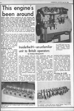
WHEN Seddon Atkinson announced the new I6-tonner 200Series machine last year the power unit created a great deal of interest. Instead of the Perkins engine Seddon Atkinson had gone for the D-358 engine from International Harvester.
As IH owns Seddon Atkinson anyway, talk at the time was that the choice of engine had been a political one, but Seddon Atkinson countered that the D-358 was chosen because its power output was more in line with their requirements.
Although the engine is a new one to British truck operators, it has nevertheless been around for a number of years in various guises and applications. My aim here is to familiarise UK operators with the unit, its past history and servicing requirements.
The 13-358 is but one part of a family of three, four and sixcylinder engines with the first two being intended mainly for farm tractors and agricultural machines. For 1976, it is anticipated that 47 versions of the engine family will be produced, the applications of which are split as follows : farm equipment (80 per cent) ; construction equipment (10 per cent) ; trucks (5 per cent) ; and miscellaneous applications (5 per cent).
The truck version of the D-358 has been in use since 1968 notably in Australia, Turkey and South Africa.
Technical details
The D-358 for the Seddon Atkinson is a naturally aspirated water-cooled sixcylinder unit of 5.87 litres (358 cu in capacity). The maximum power of 100kW (134 bhp) is produced at the comparatively high engine speed of 3000 rpm while 1600 rpm is the corresponding figure for the maximum torque of 360Nm (266 lb ft). Both these performance ratings are net installed to BS AU 141a:1971.
The integral crankcase and cylinder block is in grey cast iron while the wet cylinder liners are centrifugally cast from spheroidal graphite iron. The bore is plateau honed to keep the running-in period to a minimum. This seems to work as, on the test benches at Neuss, the engine is capable of producing full power after only 20 minutes with no problems at all. Every so often, a random sample motor is run for 5000 hours after which it is stripped to check the wear on the individual components.
The fuel-injection equipment consists of a Bosch CR distributor-type pump supplying Bosch four-hole injectors. The inlet and exhaust valves are fitted with " Rotocaps " which impart a rotation of 17° on each opening to minimise seat wear.
The aluminium alloy pistons have a toroidal combustion chamber in the piston crown and the top compression ring is retained in a steel insert. Two compression rings are fitted along with one springloaded oil-control ring.
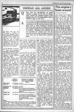
The crankshaft is dropforged from chrome-molybdenum steel with inductionhardened journals. Balance weights are bolted to the shaft by means of a type of Allen screw with an internal " star " socket requiring a special tool for removal.
However, as it is necessary to remove these only if a regrind is to be carried out, this should not be a problem to the operator. Although IH claims that three regrinds of the crankshaft journals are possible before the induction hardened surface is penetrated, to the best of their knowledge nobody has ever needed to regrind the crankshaft anyway.
The cooling system uses brass jets in the cylinder head which direct the coolant to the point where the valve seats and the injector are in close proximity. The injector itself is enclosed in a brass sleeve inserted through the water jacket for optimum heat transfer.
Servicing the D-358
International Harvester use different coloured paint to denote the various torques required for engine assembly. For example, the nuts holding down the rocker shaft are painted red and require a tightening torque of 60 to 70Nm (44 to 51 lb ft). The colour coding is a useful aid in this area as the nuts holding down the head have the same dimensions but a different torque requirement (painted yellow).
If the head is removed with the injectors in situ, it is a good idea to rest the ends of the head on a couple of wooden blocks to prevent damage to the nozzle tips which protrude slightly beyond the head face.
The rocker arms on the IH engine are of different lengths with the shorter being for the exhaust valve. If the bushes get worn it is a simple matter to drift out the old ones and replace, but it must be remembered that a new lubricating hole (3 mm or in in diameter) must be drilled in the bush. The existing passage in the rocker itself can be used as a guide.
The inlet and exhaust valves are both fitted with a single spring. The usual collet system of retention is employed at the top of each spring while the Rotocap is arranged at the lower end. A Rotocap consists of the outer ring, a ball race with extended cups for the balls, a plate spring, the balls themselves and individual coil springs.
When the valve is lifted, the balls being under spring pressure are moved against the tension of the little springs by the plate spring. The outer ring is thus turned anti-clockwise at the same time rotating the valve spring, the upper valve spring retainer and the valve itself.
The function of the Rotocap is to minimise valve-seat wear, and so if one seat is found to be pitted it could be that the Rotocap itself is at fault. This is easily checked by removing the rocker cover and revving the engine. If the valves can be seen to rotate anti-clockwise then all is well.
Valve guides for both inlet and exhaust are identical. A clearance of 0.15 mm (0.0059 in) is the maximum allowed before replacement. A special drift punch is available for the engine which ensures that the specified protrusion of the new valve guide (29.5 mm or 1.161 in) is automatically obtained.
Both inlet and exhaust valves are fitted with oil scraper rings on the stems. On assembling the cylinder head, these rings should be slid on to the valve stems and over the upper end of the guides taking care not to dislodge the Teflon ring. Final adjustment of the valve clearance should be carried out, when the engine is hot, to the following settings : exhaust valves 0.30 mm (.012 in), inlet valves 0.25 mm (.010 in). Still on the cylinder head, replacement of the brass injector sleeve deserves a mention. The sleeve extends beyond the face of the cylinder head right to the tip of the nozzle to provide some degree of heat protection.
If replacement of the sleeves becomes necessary they can be pulled out with a conventional internal extractor although if this fails a few blows with a stepped punch should provide the answer. The sealing areas of the new sleeves must be coated with Loctite before fitting, but there are no extra washers or sealing rings to worry about.
The copper cooling jets in the cylinder head are not subject to "wear and tear" in the usual manner, but if replacement is necessary a thread should be cut into the jet collar which can then be pulled out by inserting an ordinary screw. New jets are a push fit and must be flush with the cylinder head face. No extra sealing aids eg Loctite or sealing rings are necessary.
Cylinder block assembly
On the D-358 the cylinder head can be removed without moving the water pump. For access to the timing gears, however, the water pump must be removed.
A puller is recommended for removing the crankshaft pulley, but a rubber or hide mallet will do instead. A steel hammer must not be used as the pulley is made of grey cast iron, The wet-type cylinder liners are extracted with a special puller. The liners and pistons are classified dimensionally in three groups (A, B and C) by the factory for service purposes. Although it is possible to replace a piston or rings individually, IH recommends that the complete ring/piston/ liner assembly is changed to maintain a good oil consumption.
For removing the gudgeon pin a special II-1 drift is available, but for fitting it is recommended that the piston is heated in an oil bath or an oven to about 75°C (170°F) to expand.
To ensure that the combustion bowl in the piston is in the right place relative to the nozzle, the piston has " Front " stamped in the crown on the water pump side. To fit the connecting rods the right way round, the flattened areas at the little end should face the crankshaft side of the engine.
When the engine was designed IH claimed that the list of special tools which were required for overhauling the unit had been kept to the minimum. Several of these are not essential—for example most workshops will have a universal type of puller available for removing the crankshaft damper, and anyway IH turns a blind eye to removing this particular component with a mallet (provided it is a rubber or hide one) !
The same remark applies to the strap wrench for tightening the oil filter—most workshops will have one anyway,