


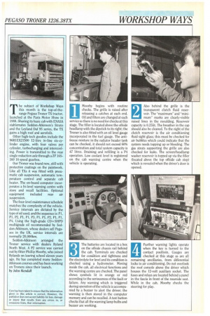
Moorby begins with routine checks. The grille is raised after
Page 93
Page 94
Page 95
Page 96
If you've noticed an error in this article please click here to report it so we can fix it.
releasing a catches at each end. Oil and filters are changed at each service so there is no need for checks at this stage. The filler is located above the offside headlamp with the dipstick to its right; the Troner is also fitted with an oil level gauge incorporated in the fuel gauge. The antifreeze mixture in the radiator header tank can be checked, it should not exceed 60% concentration and total system capacity is 47 litres. Draining and refilling is a P4 operation. Low coolant level is registered on the cab warning centre when the vehicle is operating.
1
2 Also behind the grille is the transparent clutch fluid reser voir. The "maximum" and "mini mum" marks are clearly-visible raised lines in the moulding. Reservoir capacity is 0.251it. The breather in the cap should also be cleaned. To the right of the clutch reservoir is the air conditioning fluid sight glass; this must be checked for air bubbles which could indicate that the system needs topping up or bleeding. The gas struts supporting the grille are also checked for leaks. The screen/headlamp washer reservoir is topped up via the filler (located above the top offside cab step) which is revealed when the driver's door is opened.
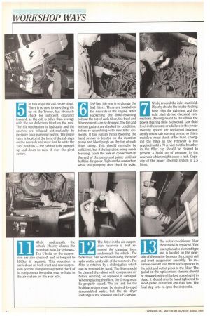
gj The batteries are located in a box on the offside chassis rail behind the cab. Terminals are checked for condition and tightness and the electrolyte for level and its condition is checked using a hydrometer. Moving inside the cab, all electrical functions and the warning centre are checked. The panel shows symbols lit in orange or red according to the seriousness of the fault or failure. Any warning which is triggered during operation of the vehicle is accompanied by a buzzer to alert the driver; the warning is then stored in the computer memory and can be recalled. A test button checks that all the warning lamp bulbs and buzzer are working. Further warning lights operate when the key is turned to the contact positioin. Gauges are checked at this stage as are all remaining ancillaries, from differential locks to air conditioning. Do not overlook the roof console above the driver which houses the 12-volt auxiliary socket. The fuses and relays are located behind a panel in the fascia in front of the nearside seat. While in the cab, Moorby checks the steering for play.
At this stage the cab can be tilted. There is no need to leave the grille up on the Troner, but obviously check for sufficient clearance forward, as the cab is taller than average with the air deflectors fitted on the roof. The tilt mechanism is hydraulic and the catches are released automatically by pressure once pumping begins. The pump valve is located at the front of the cab steps on the nearside and must first be set to the "up" position — the cab has to be pumped up and down to raise it over the pivot centre.
6 The Erst job now is to change the
fuel filters. These are located on the nearside of the engine. After slackening the bowl-retaining bolts at the top of each filter, the bowl and filter elements can be dropped. The top and bottom gaskets are checked for condition, before re-assembling with new filter elements. If the system needs bleeding the hand primer is located on the injection pump and bleed plugs on the top of each filter casing. This should normally be sufficient, but if the injection pump needs bleeding, crack the leak off connection on the end of the pump and prime until air bubbles disappear. Tighten the connection while still pumping, then check for leaks. While around the inlet manifold, Moorby checks the intake ducting hose clips for tightness and the cold start device electrical connections. Moving round to the offside the power steering fluid is checked. Low fluid level in the system or a failure in the power steering system are registered independently on the cab warning centre, so this is mainly a visual check of the fluid. Changing the filter in the reservoir is not required until a P3 service but the breather in the filler cap should be cleaned to prevent a build up of pressure in the reservoir which might cause a leak. Capacity of the power steering system is 2.5 litres.
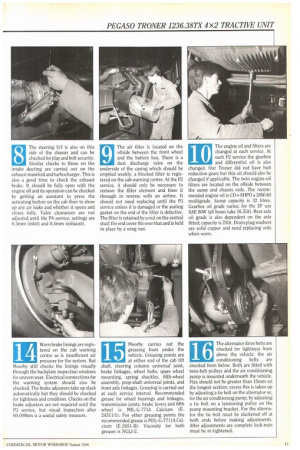
8 The steering U/1 is also on this
side of the chassis and can be checked for play and bolt security.
Similar checks to those on the intake ducting are carried out on the exhaust manifold and turbocharger. This is also a good time to check the exhaust brake. It should be fully open with the engine off and its operation can be checked by getting an assistant to press the activating button on the cab floor to show up any air leaks and whether it opens and closes fully. Valve clearances are not adjusted until the P4 service; settings are 0.3mm (inlet) and 0.4mm (exhaust).
9 The air filter is located on the
offside between the front wheel and the battery box. There is a dust discharge valve on the underside of the casing which should be emptied weekly; a blocked filter is registered on the cab warning centre. At the P2 service, it should only be necessary to remove the filter element and blow it through in reverse with an airline. It should not need replacing until the P3 service unless it is damaged or the sealing gasket on the end of the filter is defective. The filter is retained by a nut on the central stud; the end cover fits over that and is held in place by a wing nut.
10 The engine oil and filters are
changed at each service. At each P2 service the gearbox and differential oil is also changed. Our Ironer did not have hub reduction gears but this oil should also be changed if applicable. The twin engine-oil filters are located on the offside between the sump and chassis rails.. The recommended engine oil is CD +SHPD a 20W/40 multigrade. Sump capacity is 32 litres. Gearbox oil grade varies; for the ZF use SAE 80W (all boxes take 16.5lit). Rear axle oil grade is also dependent on the axle fitted; capacity is 251it. Drain plug washers are solid copper and need replacing only when worn.
11 While underneath the
vehicle Moorby checks the propshaft bolts for tightness.
The U-bolts on the suspension are also checked, and re-torqued to 470Nm if required. This operation is carried out on both front and rear suspension systems along with a general check of its components for undue wear or leaks in the air system on the rear axle. The filter in the air suspension reservoir is best removed for cleaning from underneath the vehicle. The tank must first be drained using the relief valve on the underside of the reservoir. The filter is retained by a sliding plate which can be removed by hand. The filter should be cleaned then dried with compressed air before refitting, or replaced if damaged. When replacing the filter, the 0-ring must be properly seated. The air tank for the braking system must be drained to expel accumulated water, but the air dryer cartridge is not renewed until a P3 service.
12 13 The water conditioner filter
should also be replaced. This is a replaceable element type
and is located on the nearside of the engine between the chassis rail and front suspension assembly. To minimise coolant loss there are stopcocks in the inlet and outlet pipes to the filter. The gasket on the replacement element should be smeared with oil before screwing it in place, it should only be hand tightened to avoid gasket distortion and fluid loss. The final step is to re-open the stopcocks. 14 Worn brake linings are regis
tered on the cab warning centre as is insufficient air pressure for the system. But Mcmrby still checks the linings visually through the backplate inspection windows for uneven wear. Electrical connections for the warning system should also ' be checked. The brake adjusters take up slack automatically but they should be checked for tightness and condition. Checks on the brake adjusters are not required until the P3 service, but visual inspection after 60,000km is a useful safety measure.
15 Moorby carries out the
greasing from under the vehicle. Greasing points are at either end of the cab tilt shaft, steering column universal joint, brake linkages, wheel hubs, spare wheel mounting, spring shackles, fifth-wheel assembly, prop-shaft universal joints, and front axle linkages. Greasing is carried out at each service interval. Recommended grease for wheel bearings and linkages, transmission joints, brake levers and fifth wheel is MIL-G-771A Calcium (E24511/1). For other greasing points the recommended grease is MIL-G-7711A Calcium (E-245I-B). Viscosity for both greases is NGL1-2.
16 The alternator drive belts are
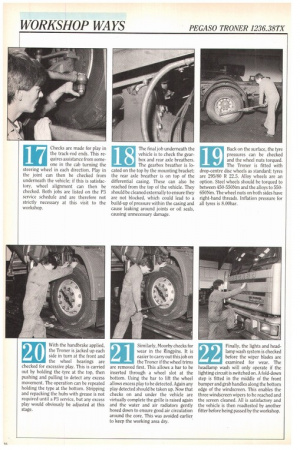
checked for tightness from above the vehicle; the air conditioning belts are checked from below. Both are fitted with twin-belt pulleys and the air conditioning pump is mounted underneath the vehicle. Flex should not be greater than 15mm on the longest section; excess flex is taken up by adjusting a tie bolt on the alternator or, for the air conditioning pump, by adjusting a tie bolt on a tensioning pulley on the pump mounting bracket. For the alternator the tie bolt must be slackened off at both ends before making adjustments. After adjustments are complete lock-nuts must be re-tightened. Checks are made for play in the track-rod ends. This requires assistance from someone in the cab turning the steering wheel in each direction. Play in the joint can then be checked from underneath the vehicle; if this is satisfactory, wheel alignment can then be checked. Both jobs are listed on the P3 service schedule and are therefore not strictly necessary at this visit to the workshop. The final job underneath the vehicle is to check the gearbox and rear axle breathers. The gearbox breather is located on the top by the mounting bracket; the rear axle breather is on top of the differential casing. These can also be reached from the top of the vehicle. They should be cleaned externally to ensure they are not blocked, which could lead to a build-up of pressure within the casing and cause leaking around joints or oil seals, causing unnecessary damage.
19 Back on the surface, the tyre
pressures can be checked and the wheel nuts torqued.
The Troner is fitted with drop-centre disc wheels as standard; tyres are 295/80 R 22.5. Alloy wheels are an option. Steel wheels should be torqued to between 450-550Nm and the alloys to 550650Nm. The wheel nuts on both sides have right-hand threads. Inflation pressure for all tyres is 8.00bar.
With the handbrake applied, the Troner is jacked up each side in turn at the front and the wheel bearings are checked for excessive play. This is carried out by holding the .tyre at the top, then pushing and pulling to detect any excess movement. The operation can be repeated holding the type at the bottom. Stripping and repacking the hubs with grease is not required until a P3 service, but any excess play would obviously be adjusted at this stage.
20 21 Similarly, Moorby checks for
wear in the Kingpins. It is easier to carry out this job on the Troner if the wheel trims are removed first. This allows a bar to be inserted through a wheel slot at the bottom. Using the bar to lift the wheel allows excess play to be detected. Again any play detected should be taken up. Now that checks on and under the vehicle are virtually complete the grille is raised again and the water and air radiators gently hosed down to ensure good air circulation around the core. This was avoided earlier to keep the working area dry.
22 Finally, the lights and head
lamp wash system is checked before the wiper blades are examined for wear. The headlamp wash will only operate if the lighting circuit is switched on. A fold-down step is fitted in the middle of the front bumper and grab handles along the bottom edge of the windscreen. This enables the three windscreen wipers to be reached and the screen cleaned. All is satisfactory and the vehicle is then roadtested by another fitter before being passed by the workshop.