


Fuel savings in the air
Page 83
Page 84
If you've noticed an error in this article please click here to report it so we can fix it.
THERE'S no surer way for an operator to economise on fuel than to get the message across to his drivers to take it easy on acceleration and braking — especially on short runs.
But for longer runs, and, of course, TIR work in particular, I am sure, writes the Technical Editor, that significant savings can be made by minimising drag, particularly through the use of air deflectors.
One manufacturer involved in intensive research in this field is Leyland Truck and Bus, with an investigation into optimum cab design for high aerodynamic efficiency. In this article, Bill Lowe, manager of the body engineering, heavy vehicle division, reports on the improvements that can be made and the fuel consumption savings that are to be had.
At 60mph, a typical 32-tonner uses around 40 per cent of its engine output, and half of its fuel requirement, just to overcome aerodynamic drag. Assuming a consumption of seven mpg at these running conditions, designing an optimum aerodynamic cab shape can provide fuel consumption savings of between eight and 16 per cent — depending on load profile.
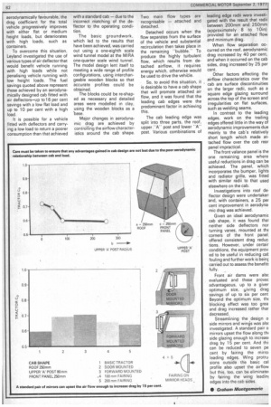
The effects of load profile on aerodynamic drag are most important and care must be taken to ensure that advantages gained in cab design are not lost either due to the poor aerodynamic performance of the load, or the poor relationship, aerodynamically, between cab and load.
Tests have shown that, as cab design becomes more aerodynamically favourable, the drag coefficient for the total vehicle progressively improves with either flat or medium height loads, but deteriorates with high loads, such as containers.
To overcome this situation, Leyland investigated the use of various types of air deflector that would benefit vehicle running with high loads while not penalising vehicle running with low height loads. The fuel savings quoted above represent those achieved by an aerodynamically designed cab fitted with air deflectors—up to 16 per cent savings with a low flat load and up to 10 per cent with a high load.
It is possible for a vehicle fitted with deflectors and carrying a low load to return a poorer consumption than that achieved with a standard cab — due to the incorrect matching of the deflector to the operating condition.
The basic groundwork, which led to the results that have been achieved, was carried out using a one-eighth scale wind tunnel model at the MIRA one-quarter scale wind tunnel. The model design lent itself to meeting a wide range of profile configurations, using interchangeable wooden blocks so that accurate profiles could be obtained.
The blocks could be re-shaped as necessary and detailed areas were modelled in clay, using the wooden blocks as a 'base.
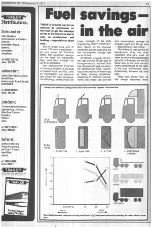
Major changes in aerodynamic drag are achieved by controlling the airflow characteristics around the cab shape. Two main flow types are recognisable — attached and detached.
Detached occurs when the flow separates from the surface of the vehicle and substantial recirculation then takes place in the remaining -bubble.To produce the highly turbulent flow, which results from detached airflow, it requires energy which, otherwise would be used to drive the vehitle.
So, to avoid this situation, it is desirable to have a cab shape that will promote attached air flow, and it was found that the leading cab edges were the predominant factor in achieving this.
The cab leading edge was split into three parts, the roof, upper -Apost and lower "A" post. Various combinations of
leading edge radii were investigated with the result that radii between 200mm and 250mm (approximately 8 to 10in) provided for an attached flow and minimum drag_ When flow separation occurred on the roof, aerodynamic drag increased by 40 per cent, and when it occurred on the cab sides, drag increased by 25 per cent.
Other factors affecting the airflow characteristics over the cab are surface discontinuities on the larger radii, such as a square edge glazing surround across the top of the screen and irregularities on flat surfaces, such as welding seams.
In contrast to the leading edges, work on the trailing edges offered little in the way of aerodynamic improvements due mainly to the cab's relatively short length which made attached flow over the cab rear panel impractical.
The front valance panel is the one remaining area where useful reductions in drag can be achieved. The panel, which incorporates the bumper, lights and radiator grille, was fitted with similar radii to that used elsewhere on the cab.
Investigations into roof deflector design were undertaker and, with containers, a 25 per cent improvement in aerodynamic drag was achieved.
Given an ideal aerodynamic cab shape, it was found tha' neither side deflectors nor turning vanes, mounted at thE corners of the front panel, offered consistent drag reduc. tions. However, under certair conditions, the equipment prov ed to be useful in reducing caL fouling and further work is beinç carried out to assess the benefit: fully.
Front air dams were alsc eva!uated and these provec advantageous, up to a giver optimum size, yiving drag savings of up to six per cent Beyond the optimum size, th( blocking effect was too grea and drag increased rather thar decreased.
Streamlining the ,design o side mirrors and wings was els( investigated. A standard pair o mirrors upset the flow along thi side glazing enough to increasi drag by 15 per cent. And thr can be reduced to seven pe cent by fairing the mirro. leading edges. Wing protru sions outside the basic cal profile also upset the airflow but this, too, can be eliminate( by fairing the wing leadinl edges into the cab sides.
• Graham Mon tgomerie