


Gear Ratios Doubled by Employing Two Clutches
Page 60
If you've noticed an error in this article please click here to report it so we can fix it.
PATENT No. 622,786 comes from Morris Motors, Ltd., H. Merritt and D. Foweraker, all of Cowley, Oxon, and shows a transmission having two clutches. The aim is to provide, in addition to the usual gear-ratios, an optional step-down which, in effect, doubles the number of speeds.
In the drawing, a forward clutchplate (1) drives an inner shaft (2) attached to the input member of the normal gearbox (3). A second clutchplate (4) drives a tubular shaft terminating in a pinion (5). This drives a gear (6) which is journalled on a layshaft (7) common to both the main and auxiliary gearboxes. A pair of constant-mesh gears (8 and 9) can also drive the main gearbox input, but as this may already be being driven by shaft 2, an over running clutch t(0) is provided.
1 n operation, if both clutches be engage d, a straightthrough drive is transmitted, the ove rrunning clutch freewheeling the while. Rut if only the rear clutch be engaged, the drive is transmitted in a lower ratio through the gears 5; 6, 8•and 9.
Other features of the scheme are the provision of centrifugally operated TRAILER COUPLING HAS RUBBER BUSHING
TOprovide resilience and to prevent rattle in a trailer drawbar coupling is the object of a scheme shown in patent No. 623.433, by A. Dear and J. Brock house and Co., Ltd., Victoria .Works, Hill Top, West 13romwich.
The drawing shows the wellknown Brockhouse coupling with the improvements added. The spherical joint is, in this case, lined with rubber (1), the loading on which can be initially adjusted, and later taken up for wear, by means of a screwed plug (2). The rubber part is actually made in two pieces, upper and lower, for reasons of assembly.
a34 Not only does the scheme reduce wear and prevent rattle, but it also reduces manufacturing costs, as a high degree of accuracy in the spherical machining is no longer required.
SEALING WASHER FOR HYDRAULIC BRAKES
ONE-WAY sealing washers cf the thin lip-type have been used in the master-cylinders of
hydraulic brakes, but they have • proved to be unsatisfactory owing to the rapid wear on the lips: Such is the view of the Wingfoot Corporation, Akron, Ohio, U.S.A., which discloses, in patent No. 623,397, a one-way sealing washer without lips.
The drawing shows the piston of a mastercylinder with the improved ring in position. The ring (I) is made of rubber and has a circular crosssection. Its dimensions are such that it is radially compressed between. cylinder and piston when in .the position shown. When the piston is moved to the right, the Auld pressure increases the load on the ring and this renders it self-sealing. When moved to the left, however, the diminishing diameter (2) of the piston allows the ring to remain behind for a short, distance, and so give the open position in which fluid can freely get by. The trailing action is limited by a washer (3) screwed to the end of the piston. To make quite certain that the ring dislodges at the end of the stroke, a push-off washer (4) is provided; this is worked by a rod (5) which makes contact with a stationary part.
The scheme appears to be a remarkably simple one. RUBBER BUSHING FOR STARTER PINIONS
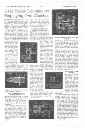
TO impart a 'measure of resilience to the engaging action of an electric starter is the aim of a modified type of pinion shown in patent No. 623,349, by Joseph Lucas, Ltd., and• C. Robinson, both of Great King Street, Birmingham, 19.
In the drawing, I is the usual quickthreaded sleeve through which the pinion (2) is driven. The method of connecting the two parts consists of a nut (3) bonded to a rubber bush (4) which is further bonded to an outer metal -`sleeve (5). At the other end of the sleeve another rubber bush (6) similarly joins the sleeve to. the pinion. There are thus otwo rubber members in series, giving extra torsional .flexibility. Actually, the outer sleeve Is made in two parts, joined by interlocking dogs in the middle, and permanently united by a spun-over metal shell (7).
INJECTION PUMP , TIMING
PATENT NO. 622,379, which comes from Lagonda, Ltd., and others, L a go n da Works, Staines, shows a means for finelY ad-, lusting the output of the individual plungers of an injection pump. The chief aim is to provide a means for making the adjustment simply and quickly without any dismantling.
The pump referred to is of the type having a camshaft which operates the plungers through the medium of rockers. In the drawing, 1 is the body of the pump, 2 the bell-mouthed end of a plunger, and 3 the rocker. The motion is transmitted via push-rods (4) and the method of adjustment is to substitute another push-rodof slightly different length, a selection of these being kept on hand for the • purpose. The method alters the top and bottom positions of the plunger, but the amount is negligible apart from the desired timing variation. A slot (5) in the lower " bell" assists in the removal of the rod already in place. The one objection is the need for spare rods.