


Apportioning Braking Effort
Page 56
If you've noticed an error in this article please click here to report it so we can fix it.
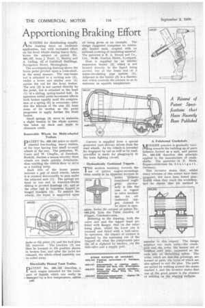
ASCHEME for distributing equally the braking force on moderate application, but with increased effort on the front wheels during heavy duty, forms the subject of patent No. 489,187, from J. Pratt, G. Manley and A. flirting, all of Guildhall Buildings, Navigation Street, Birmingham.
The accompanying drawing shows the brake pedal pivoted upon a cross-shaft, in the usual manner. The rear-brake rod is attached to a rocking arm (2), whilst a lower and similar arm (4) carries the rod for the front brakes. The arm (2) is not carried directly by the pedal, but is attached to the head (1) of a sliding, spring-loaded bolt. In operation initial pedal movement affects both brakes equally until the compression of a spring (5) is overcome ; after this the fulcrum of the arm (2) loses some of its motion as the pedal progresses to apply further the front brakes.
Small springs (3) serve to maintain a slight tension in the whole system; this takes up slack and tends to eliminate rattle.
Removable Wheels for Multi-wheeled Trailers.
PATENT No. 489,183 refers tomultiwheeled low-loading, heavy trailers, of the type having four small co-axial wheels at the rear. The patentees, W. Crane and W. Chaplin, of Derelaam, Norfolk, disclose a means whereby these wheels are made quickly detachable, thus enabling the vehicle Aloor to serve as a loading ramp. ,
Each side of the frame passes between a pair of small wheels, where it is cranked downwardly to pass under the adjacent axle (1). The springs are fixed at one end to trunnion-blocks sliding in pivoted housings (4), and at the other end to trunnions housed .in hinged braclrets (3); . To ,rernOve the wheels, the frame is supported: upon jacks at the point (5) and the lock-pins (2) removed. The brackets (3) can then be lowered to the position shown in broken line, and after the jacks are released, the whole wheel assembly can be rolled away.
Electrically Heated Tank Trailer.
PATENT No. 489,120 describes. a tank wagon intended for the trans: port of liquids which can easily be cclamaged.by. a -low -temperature, edible
B46 oil being given as an example. The design suggested comprises an internally heated tank, coupled with an external covering of insulating material. The patentee is R. A. Dyson and Co., Ltd., 76-80, Grafton Street, Liverpool.
Heat is , supplied. by an electric' immersion heater (2)' which is not located directly in the liquid being carried, but at the lower end of a water-circulating pipe system (1). Adjacent to the heater (2) is a thermostat which controls the current so as to maintain an equable temperature.
Current is supplied from a special generator (not shown) driven from the road wheels. As the vehicle is intended for trapport by rail as well as by road. provision is made for plugging-in to the train lighting circuit.
• Hydraulically Cushioned Tappets.
THE modern tendency towards the useof rubber engine-mountings often results in an apparent increase in
• • noieei hitherto . c'onsidered' negii
. gible; particularly is this the'. case in regard to valve mechanism. An oilcushioned tippet, claimed to be silent in operation, forms. the subject pf patent No. 489,216, from the Tatra concern, of Prague, Czechoslovakia.
Referring to the drawing, both the valve end and the tappet head are fitted with flanges, that on the valye • being plain, whilst the lower one is recessed and fitted with a ball-valve. In operation, the impact of contact is lessened by the squeezing out of the trapped oil; when the components part the on is replaeed. by siction, via the ball-valve and a supplY Port.
WAN%
11
z
A Fabricated Crankshaft.
AODERN practice is gradually tendJ.Vling towards the building up of parts hitherto formed as a unit, and patent No. 489,326 describes this principle applied to the manufacture of crankshafts. The patenteeis H. Hirth, Bopserwaldstrasse 54; Stuttgart. Germany, This inventor states that, whilst many schemes of this nature have been proposed, few have been found practicable when they reach the workshop, And :le claims that his method is
superior in this respect. The design employs two main units—the crankpins and _the webs; the former are of weldless steel tube, expanded at the ends into an "undulating spline. The webs, which are dish-like pressings, are formed as pairs, the bores of which are also splined to suit the pins. The parts are united by welding around the seams marked 1, and the inventor states that one of the good points is the absence _ of welding on the wearing su4aces.